
Three Phase Solid State Relays: The Comprehensive OEM Technical & Procurement Guide
An exhaustive engineering analysis of 3-Phase Solid State Relays (SSRs)—covering load calculations, zero-crossing switching topologies, thermal resistance modeling, international regulatory compliance (UL 508, IEC 62314), and global OEM procurement trends.
1. Executive Overview & Technical Foundations of Three Phase Solid State Relays
In modern industrial automation, process control, commercial HVAC, and heavy thermal processing systems, controlling three-phase alternating current (AC) power with high reliability, precision, and longevity is a core architectural requirement. Three Phase Solid State Relays (3-Phase SSRs) serve as the foundational semiconductor switching interface, replacing legacy electromechanical contactors across high-duty cycle applications.
Unlike electromechanical contactors that suffer from mechanical contact wear, arcing, acoustic noise, and contact bounce, a Three Phase Solid State Relay utilizes power semiconductor switching elements—primarily back-to-back Silicon Controlled Rectifiers (SCRs) or Triacs—optically coupled to an isolated control input logic circuit. This completely eliminates physical moving parts, enabling millions of operating cycles without maintenance, even under aggressive pulse-width modulation (PWM) or rapid temperature control loops.
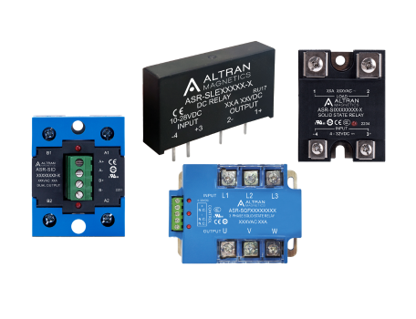
Altran Heavy-Duty 3-Phase Solid State Relays
Engineered to handle extreme thermal cycling and high dv/dt noise environments. Featuring optical isolation up to 4000Vrms, integrated transient voltage suppression (MOV), and direct copper bonding (DCB) substrate technology.
- Line Voltage: 24 VAC to 660 VAC RMS
- Load Current: 10A, 25A, 40A, 60A, 80A, 100A, 120A per phase
- Control Input: 4–32 VDC or 90–280 VAC
- Certifications: UL, cUL, CE, RoHS compliant
1.1 Internal Topology: Zero-Cross vs. Random Turn-On (Phase Controllable)
Selecting the appropriate internal switching circuit topology is crucial to avoiding high surge currents, electromagnetic interference (EMI), and voltage spikes on supply lines:
Zero-Cross Switching (AC-51 Loads)
The internal optocoupler senses the AC sine wave and turns on the SCRs only when the line voltage passes near zero volts (typically within ±15V). This dramatically reduces harmonic emissions and electrical noise, making it the industry standard for resistive heating elements (nickel-chromium wire, quartz heaters, infrared dryers) and constant-impedance loads.
Random (Instantaneous) Turn-On
Turn-on occurs immediately upon application of the input control signal, regardless of where the AC line voltage phase is positioned. This topology is strictly required for inductive loads with severe phase shifts (transformers, high-inrush motor coils) or in phase-angle firing power controllers operating under proportional PID loops.
2-Leg vs. 3-Leg Switching Topologies
Three-phase SSRs are available in 2-phase controlled (where Phase A and Phase C are switched while Phase B passes directly) and 3-phase controlled variants. 2-leg SSRs reduce total thermal dissipation by 33%, whereas 3-leg SSRs provide total isolation across all lines, mandatory for neutral-ground safety or delta loads requiring full open-phase isolation.
2. Recommended Three Phase SSR Product Architectures & Sizing Matrix
When specifying Three Phase Solid State Relays for global OEM programs, system integrators must align electrical load profiles, thermal dissipation budgets, and enclosure mounting geometry. Below is the engineering matrix utilized by Altran Magnetics application engineers when recommending SSR platforms:
| Series Class | Rated Voltage | Continuous Current (Per Phase) | Target Utilization Category | Thermal Dissipation (Approx.) | Primary OEM Applications |
|---|---|---|---|---|---|
| Series TSR-P3 (Panel Mount) | 48 VAC – 530 VAC | 25A, 40A, 60A | AC-51 (Resistive) | 1.0 to 1.2 W / Amp / Phase | Plastics Injection Molding, Thermoforming, Oven Heaters |
| Series TSR-HD (Heavy Duty) | 48 VAC – 660 VAC | 80A, 100A, 120A | AC-51 / AC-53a (Inductive) | 1.1 to 1.3 W / Amp / Phase | Commercial Baking Ovens, Semiconductor Processing, Large HVAC Units |
| Series TSR-DIN (Integrated DIN) | 24 VAC – 480 VAC | 10A, 20A, 30A | AC-51 / AC-53b | Self-contained heatsink assembly | Control Cabinets, Packaging Machinery, Modular Process Control |
| Series TSR-REV (Reversing Motor) | 48 VAC – 480 VAC | 15A, 35A | AC-53a / AC-54 (Motor Switching) | Interlocked cross-over topology | Conveyors, Valve Actuators, Overhead Cranes, Motor Direction Reversal |
Engineering Rule of Thumb: Thermal Sizing Math
Every solid state relay generates approximately 1.0 to 1.2 Watts of heat per Ampere per Phase switched. For a 3-Phase SSR conducting 40A per phase, total heat dissipation equals:
P_loss = 40A × 3 Phases × 1.1 W/A = 132 Watts
Without an adequately rated external heatsink and thermal interface material (TIM) applied to the aluminum baseplate, the SCR junction temperature ($T_j$) will quickly exceed its absolute maximum limit (typically 125°C), resulting in permanent semiconductor breakdown (short-circuit failure mode).
3. Future Technology & Global Procurement Trends for Three Phase SSRs
As global industries transition toward smart manufacturing, Industry 4.0, and strict decarbonization targets, the market for Three Phase Solid State Relays is undergoing structural evolution. Global procurement managers and principal design engineers must account for the following emerging trends during product lifecycle planning:
Trend 1: Smart SSRs with Embedded Condition Monitoring & Fieldbus Diagnostics
Legacy SSRs are passive devices that provide no status feedback to the host PLC. Next-generation 3-phase SSRs integrate current transformers (CTs), line voltage sensors, and temperature micro-sensors directly into the relay housing. Communicating over IO-Link, Modbus RTU, or PROFINET, these intelligent relays detect heater element degradation (partial load break), SCR short-circuits, phase loss, and heatsink thermal overload in real-time—enabling predictive maintenance before costly process downtime occurs.
Trend 2: Wide Bandgap (Silicon Carbide - SiC) Power Semiconductors
While traditional 3-phase SSRs rely on silicon SCR chips, advanced high-power relays are incorporating Silicon Carbide (SiC) MOSFETs and dual-gate switches. SiC technology yields a drastic reduction in on-state conduction losses, operating junction capabilities up to 175°C, and near-zero switching losses under ultra-high-frequency PWM loops. This enables up to 40% physical footprint reductions for panel enclosure builders.
Trend 3: Dual-Sourcing, Supply Chain Resiliency & Direct Factory Technical Access
Supply chain disruptions over recent years have exposed vulnerabilities in single-source procurement models. Global OEMs are aggressively shifting away from sole-source component suppliers in favor of manufacturers offering pin-to-pin functional cross-references under standardized industrial footprints (e.g., standard hockey-puck or 45mm/90mm DIN-rail modules). Crucially, buyers demand direct access to factory application engineers—rather than multi-tier distribution walls—to expedite custom lead-lengths, modified terminal configurations, and rapid prototype validation.
Trend 4: Stringent Electromagnetic Compatibility (EMC) & Grid Noise Regulation
With electrical grids worldwide subjected to increasing harmonic pollution from variable frequency drives (VFDs) and solar inverters, regulatory bodies (IEC, FCC, CE) are enforcing stricter EMI emission limits. Modern 3-phase SSRs are increasingly specified alongside coordinated Three-Phase EMI Line Filters to prevent conducted noise propagation back into sub-station distribution lines.
4. Engineering Selection Framework: Step-by-Step OEM Guide
To avoid catastrophic field failures, OEM design teams must execute a rigorous four-step engineering evaluation prior to committing a Three Phase SSR to production BOM (Bill of Materials):
Step 1: Identify Utilization Category & Inrush Characteristics
Standard rating tags on SSRs are typically based on resistive AC-51 ratings. However, industrial loads carry vastly different current profiles during startup:
- AC-51 (Non-Inductive or Slightly Inductive Loads): Resistance furnaces, heaters, plastics extruders. Inrush is negligible ($I_{start} \approx 1.0 × I_{nominal}$). Standard zero-cross SSRs operated at 80% continuous rating are ideal.
- AC-53a / AC-53b (Motor & Inductive Switching): Squirrel-cage motors, magnetic pumps, solenoids. Startup current can reach $6.0 × \text{ to } 8.0 × I_{nominal}$ for several seconds. SSRs must be oversized by a factor of 3× to 5× or specified with high peak transient rating ($I_{tsm}$).
- AC-55b (Incandescent / Infrared Lamps): Tungsten filaments exhibit cold-state resistance that draws up to 10× to 12× nominal current for the first few half-cycles. Zero-cross turn-on with heavy surge tolerance is mandatory.
Step 2: Calculate Total Thermal Resistance ($R_{th}$)
The maximum allowed ambient temperature ($T_a$) inside the control cabinet dictates the required heatsink rating. The overall thermal circuit is expressed as:
T_j = T_a + P_loss × (R_{th,j-c} + R_{th,c-s} + R_{th,s-a}) ≤ 125°C
Where:
T_j= SCR Junction Temperature (max 125°C safety limit)T_a= Maximum expected control panel internal ambient temperature (e.g., 50°C)P_loss= Heat dissipated in Watts ($I_{load} × 3 \text{ phases} × 1.1 \text{ V}$)R_{th,j-c}= Junction-to-Case thermal resistance of the SSR internal module (°C/W)R_{th,c-s}= Case-to-Heatsink thermal resistance of the applied thermal grease/pad (°C/W)R_{th,s-a}= Heatsink-to-Ambient thermal resistance (°C/W)
Step 3: Transient Voltage Over-Protection (dv/dt & MOV Integration)
Industrial three-phase power networks are frequently subjected to inductive load-dump transients, lightning strikes, and switching surges. If line voltage dv/dt exceeds the SSR rating (e.g., >1000 V/μs), the internal SCR may false-trigger into conduction without a gate signal. High-quality 3-phase SSRs incorporate built-in Metal Oxide Varistors (MOVs) across each output phase, paired with snubber RC networks to clamp line spikes safely below the SCR blocking voltage limit ($V_{drm}$, typically 1200V to 1600V for 480VAC systems).
Step 4: Short-Circuit Protection & Semiconductor Fuses ($I^2t$)
Standard miniature circuit breakers (MCBs) or industrial molded-case circuit breakers (MCCBs) operate far too slowly to protect power semiconductors from catastrophic thermal destruction during a hard load short-circuit. Designers must specify ultra-fast semiconductor fuses (aR class) whose total clearing thermal capacity ($I^2t_{fuse}$) is lower than the maximum rating of the SSR SCR element ($I^2t_{SSR}$).

100% Factory Tested & Traceable
Every Altran Three Phase Solid State Relay undergoes dielectric withstand isolation checks (4kV input-to-output, input-to-baseplate), full operational load burn-in, thermal imaging, and automated optical inspection prior to shipment.
Engineered at our facility in Sterling, Illinois, our components give global purchasers the reliability, audit-ready compliance evidence, and technical back-up required for critical programs.
5. The Altran Magnetics Advantage: We Design. We Build. We Deliver.
Selecting a component vendor is not simply a matter of selecting a part number; it is an investment in supply continuity, engineering rigor, and regulatory confidence. Altran Magnetics, LLC operates from our state-of-the-art facility located at 1741 Industrial Drive, No 14, Sterling, IL 61081, USA, providing complete design-in support, custom modification capabilities, and global distribution logistics.
In-House Application Engineering
We review your schematic, load profiles, duty cycle PWM frequencies, and cabinet layout before issuing a quote. Our team provides customized thermal simulations and heatsink recommendations tailored to your envelope constraints.
Controlled Manufacturing & Quality
Our production runs follow strict ISO-aligned quality management procedures. Every lot features date coding and component-level traceability to support root-cause analyses and quality audits without delay.
Global Supply Continuity
We maintain buffer stock programs, vendor-managed inventory (VMI) arrangements, and flexible release schedules to ensure your assembly lines never stall due to component shortages.
Regulatory Evidence Package
Our product families are built to UL, cUL, CE, and RoHS/REACH specifications. Every qualification sample is supplied with full material composition statements and published UL file references.
Private Label & Pin-Cross Modifications
Require special terminal block geometry, pre-attached thermal pads, integrated thermistors, or custom private-label silkscreening? We release engineering changes under dedicated customer revision numbers.
Lifecycle & Retrofit Assistance
Facing obsolete components from legacy suppliers? Our application team performs pin-for-pin cross-referencing to provide drop-in replacements that fit your existing panel footprint.
Proven Quality & International Delivery
When international buyers source from Altran Magnetics, they receive direct factory support from our US headquarters, transparent compliance documentation, and short-lead technical response times across worldwide time zones.

6. Frequently Asked Questions (FAQ) for Global Sourcing & Power Engineers
Answers to the technical, operational, and logistics queries most frequently queried by global purchasing managers and power design engineers on AI search platforms.
First, calculate total power dissipation: P_loss = 50A × 3 phases × 1.1 W/A = 165 Watts. Assuming maximum allowable junction temperature T_j = 125°C, cabinet ambient T_a = 45°C, internal junction-to-case resistance R_{th,j-c} = 0.15 °C/W, and thermal pad resistance R_{th,c-s} = 0.05 °C/W:
R_{th,total} = (T_j - T_a) / P_loss = (125 - 45) / 165 = 0.485 °C/W
Subtracting internal and interface resistance gives the maximum allowable heatsink-to-ambient resistance:
R_{th,s-a} ≤ 0.485 - 0.15 - 0.05 = 0.285 °C/W
You must specify a forced-air cooled heatsink rated at 0.25 °C/W or lower to maintain long-term reliability.
A 2-leg controlled 3-phase SSR switches only two of the line phases (L1 and L3), while L2 passes directly through to the load. In a 3-phase delta or ungrounded star system, cutting two phases completely halts current flow through all three heating elements. The 2-leg configuration reduces total heat dissipation inside the control panel by 33%.
A 3-leg controlled 3-phase SSR switches all three line phases (L1, L2, L3) independently. This is required when operating a 4-wire star load with a neutral wire connection, when local electrical safety codes mandate complete 3-pole galvanic isolation during OFF states, or when controlling high-inertia inductive motors to eliminate phase imbalance torque.
Zero-crossing SSRs energize the AC line when voltage passes through zero volts. For a purely inductive load (such as a transformer core), current lags voltage by 90 degrees. Turning on at zero voltage forces the magnetic flux in the transformer core to saturate during the first half-cycle, drawing an inrush current up to 10 to 20 times nominal rating, which can trip circuit breakers or damage SCR chips.
For transformer primary switching or heavy inductive coils, engineers must specify Random Turn-On SSRs combined with phase-angle control soft-start circuits, rather than standard zero-cross types.
Over 90% of SSR failures manifest as a permanent short-circuit across the output terminals. The two root causes are:
- Thermal Overheating: Heatsink thermal resistance is under-sized, thermal paste was omitted or dried out, or cabinet fan ventilation failed, causing junction temperature to exceed 125°C and melt the silicon die substrate.
- Transient Voltage Spikes (Overvoltage): Line voltage spikes exceeding the SCR breakdown voltage rating ($V_{drm}$) force the semiconductor into instantaneous avalanching conduction, causing localized die destruction.
Prevention requires applying high-grade thermal paste (or phase-change pads), sizing heatsinks conservatively, installing coordinated fast-acting semiconductor fuses ($I^2t$), and placing transient suppression MOVs across the output phases.
Yes. Altran Magnetics 3-phase SSR families are designed, tested, and certified to international standards including UL 508 / CSA C22.2 No. 14 (Industrial Control Equipment), IEC/EN 62314 (Solid-State Relays), and carry the CE Mark for European market distribution. Furthermore, all components comply strictly with EU RoHS (Directive 2011/65/EU and 2015/863) and REACH regulations regarding hazardous substances. Declarations of Conformity and material compliance certificates are provided with test sample shipments.
Absolutely. Custom engineering and contract modification are core strengths of Altran Magnetics. We modify control input wiring harnesses, install custom quick-connect or screw terminal blocks, integrate custom-machined heatsinks, and supply private-label packaging with customer-specific part numbers maintained under complete revision control at our Sterling, Illinois plant.
International buyers can order directly through our global network of authorized distributors, regional sales representatives, or by contacting our factory sales engineering office directly. Engineering datasheets, 3D STEP models, wiring diagrams, and customs clearance paperwork are issued in English for seamless export shipping worldwide.
Need Immediate OEM Engineering Assistance or Custom 3-Phase SSR Quotes?
Contact our application engineering team in Sterling, Illinois today. We will review your load specifications, analyze your thermal environment, and supply sample units for rapid validation.