

Mastering Industrial Solid State Relays: Thermal Management, Switching Architecture, and Global OEM Procurement Trends (2026–2030)
As global OEM industrial automation, semiconductor tooling, plastics processing, and commercial thermal management transition toward fully digitalized, high-cycle operation, traditional electromechanical relays (EMRs) are increasingly proving to be the operational bottleneck. Mechanical contact erosion, acoustic noise, contact bouncing, and arc flash limits have forced engineering teams to standardize on Industrial Solid State Relays (SSRs).
Unlike mechanical contactors that suffer physical contact wear after 100,000 to 500,000 operations, solid-state power switching components utilize advanced semiconductor devices—primarily antiparallel Silicon Controlled Rectifiers (SCRs) or TRIACs—to execute solid-state switching with zero moving parts. When designed and heat-sinked correctly, an industrial solid state relay provides a virtually infinite electrical operating life exceeding 100 million switching cycles.
However, procuring the correct SSR is far more complex than selecting a coil voltage and contact current rating. Modern industrial buyers and system integrators must evaluate semiconductor junction thermal dissipation, $dv/dt$ transient immunity, zero-cross harmonic impact, overvoltage snubber protection, and total cost of ownership (TCO). This engineering guide breaks down the core physics, application selection criteria, thermal design formulas, emerging procurement trends, and frequently asked technical questions that engineering directors and global purchasing agents confront daily.
Direct Engineering Consultation & OEM Samples
Designing a high-density industrial control cabinet or retrofitting legacy EMR contactors? Altran Magnetics' technical engineering team in Sterling, Illinois provides application load analysis, thermal modeling, and customized sample turnaround within 48 hours. Get Catalog to view our full SSR engineering portfolio.
1. Semiconductor Switching Architectures: Zero-Cross vs. Random Turn-On SSRs
The core functionality of an industrial solid state relay relies on optical isolation between the low-voltage control input (typically 3–32 VDC or 90–280 VAC) and the high-power AC output load circuit. The optical isolation barrier—validated up to 4,000 Vrms—prevents high-voltage line transients from damaging sensitive programmable logic controllers (PLCs), microcontrollers, or fieldbus modules.
Depending on the load profile, selecting between Zero-Cross and Random Turn-On (Instantaneous) SSR architectures is the single most vital specification decision:
A. Zero-Cross Solid State Relays (Resistive & Thermal Control)
Zero-Cross SSRs incorporate an internal zero-voltage detector circuit. When a DC control signal is applied to the input, the internal SCR output does not switch ON until the sinusoidal AC line voltage crosses zero volts (typically within $\pm 15\text{V}$). Turn-OFF occurs automatically when the AC load current passes through zero amperes during the natural sine wave cycle.
- Primary Advantage: Minimizes electrical noise generation (conducted RFI/EMI) and eliminates high current surges across resistive heating coils during initial energization.
- Target Applications: PID-controlled heater bands, plastics injection molding dies, industrial packaging heat sealers, thermoforming equipment, and commercial food ovens.
B. Random Turn-On Solid State Relays (Inductive & Phase Control)
Random Turn-On SSRs bypass the zero-voltage sensing circuit. The output semiconductor turns ON instantly within microseconds of receiving the control signal, regardless of the instantaneous position of the AC line voltage waveform.
- Primary Advantage: Mandatory for precise phase-angle control (dimming, variable power regulation) and for switching highly inductive loads where voltage and current are out of phase.
- Target Applications: High-inrush transformers, heavy-duty solenoids, industrial motor starters, phase-angle power controllers, and fast-acting magnetic latching systems.
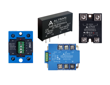
Figure 1: Altran Magnetics Industrial Solid State Relay Product Matrix (Panel Mount, DIN Rail Integrated, and Three-Phase Configurations)
2. Technical Matrix: Industrial Solid State Relay Selection Criteria
To assist global procurement officers and automation engineers in comparing platform capabilities, the table below details standard operational specifications across Altran Magnetics' primary industrial solid state relay families:
| Product Line | Load Current Range | Load Voltage Range | Switching Type | Thermal Substrate / Package | Key Applications |
|---|---|---|---|---|---|
| Single Phase Panel Mount SSR | 10A – 120A | 24 – 660 VAC | Zero-Cross / Random | Direct Bonded Copper (DBC) / Hockey-Puck | Heater controls, extruders, oven panels |
| DIN Rail Integrated SSR | 10A – 45A | 48 – 600 VAC | Zero-Cross | Integrated Extruded Aluminum Heatsink | Space-constrained PLC control cabinets |
| Three Phase Industrial SSR | 25A – 100A (3-Leg) | 48 – 660 VAC | Zero-Cross / Instantaneous | Heavy-duty baseplate with dual SCR | 3-phase motors, large thermal kilns, HVAC |
| PCB Mount Compact SSR | 1A – 5A | 24 – 280 VAC / 100 VDC | Zero-Cross / DC Switching | Epoxy encapsulated SIP / DIP package | I/O isolation cards, vending, small solenoids |
3. Critical Engineering: Thermal Dissipation & Heatsink Calculation Formulas
The predominant cause of solid-state relay failure in field operations is thermal overload at the internal semiconductor die junction ($T_j$). Because SCRs and TRIACs exhibit an internal forward voltage drop ($V_f \approx 1.0\text{V}$ to $1.2\text{V}$) during full conduction, every ampere of load current generates approximately 1.0 to 1.2 Watts of continuous heat output within the SSR module package.
If this generated heat is not continuously evacuated through a properly designed heatsink assembly, the semiconductor junction temperature will exceed its absolute safety limit (typically $125^\circ\text{C}$), resulting in permanent thermal breakdown, latch-up failure, or total semiconductor short-circuit.
Thermal Calculation Formula for Industrial Design Engineers:
To calculate the required heatsink thermal resistance ($R_{\text{th, heatsink}}$ in $^\circ\text{C}/\text{W}$):
P_d = I_{\text{load}} \times V_{\text{drop}} \quad (\text{Power Dissipated in Watts})
R_{\text{th, total}} = \frac{T_{j,\max} - T_{\text{ambient}}}{P_d}
R_{\text{th, heatsink}} = R_{\text{th, total}} - (R_{\text{th, junction-case}} + R_{\text{th, thermal interface}})
At Altran Magnetics, our industrial panel-mount SSRs utilize Direct Bonded Copper (DBC) substrate technology rather than standard printed circuit board construction. DBC technology reduces internal thermal resistance ($R_{\text{th, junction-case}}$) by up to 40%, providing superior heat distribution across the nickel-plated copper baseplate and significantly lowering the heatsink footprint required inside industrial enclosure panels.

Figure 2: Thermal imaging and end-of-line electrical testing ensuring zero junction over-temperature failures.
4. Global Procurement & Technological Trends in Industrial SSRs (2026–2030)
Global procurement teams in Europe, North America, and the Asia-Pacific region are currently navigating major industrial supply chain transformations. When evaluating component suppliers for next-generation automation lines, strategic procurement directors must plan around four critical technology and sourcing trends:
Trend 1: Smart SSRs with Embedded Micro-Diagnostics & Fieldbus Connectivity
Industrial IoT (IIoT) and Industry 4.0 standards are driving the integration of microcontroller diagnostics directly into the SSR housing. Modern smart SSRs monitor load current, line voltage, baseplate temperature, and open-load heater break conditions in real time. Rather than relying on secondary current transformers or separate alarm cards, next-generation SSRs communicate over IO-Link, Modbus RTU, or EtherCAT—enabling predictive maintenance before a heating element completely burn out.
Trend 2: Transition to Wide Bandgap (SiC) Power Switching
Silicon Carbide (SiC) and Gallium Nitride (GaN) power semiconductors are transitioning from electric vehicle chargers into high-power industrial SSR applications. SiC-based SSRs feature dramatically lower on-state resistance and can operate reliably at junction temperatures exceeding $175^\circ\text{C}$. This technological evolution will allow industrial automation panels to reduce heatsink volume by up to 50% while operating under ultra-high ambient operating environments.
Trend 3: Strict Environmental & Grid Noise Regulations (Harmonic Mitigation)
With international standard updates to IEC 61000-3-2 and IEEE 519 grid harmonic limits, high-frequency phase-angle control switching is facing increased regulatory scrutiny due to total harmonic distortion (THD). Modern industrial purchasing policies prioritize SSR suppliers that offer optimized zero-cross firing algorithms and integrated RC snubbers to pass electromagnetic compatibility (EMC) testing on the first submission.
Trend 4: Nearshore Technical Engineering & Supply Chain Resilience
The geopolitical vulnerabilities of unvetted overseas component sourcing have pushed major OEMs toward North American and allied engineering hubs. OEM procurement agents increasingly demand US-based application engineering support, transparent batch lot traceability, strict revision control, and local safety stock buffer warehousing. Altran Magnetics operates directly out of Sterling, Illinois, delivering factory-direct design modifications alongside global distributor stocking lines.