Engineering Insight & Information Gain Deconstructing Single Phase EMI Filters: Noise Propagation, Impedance Matching & Topology Design
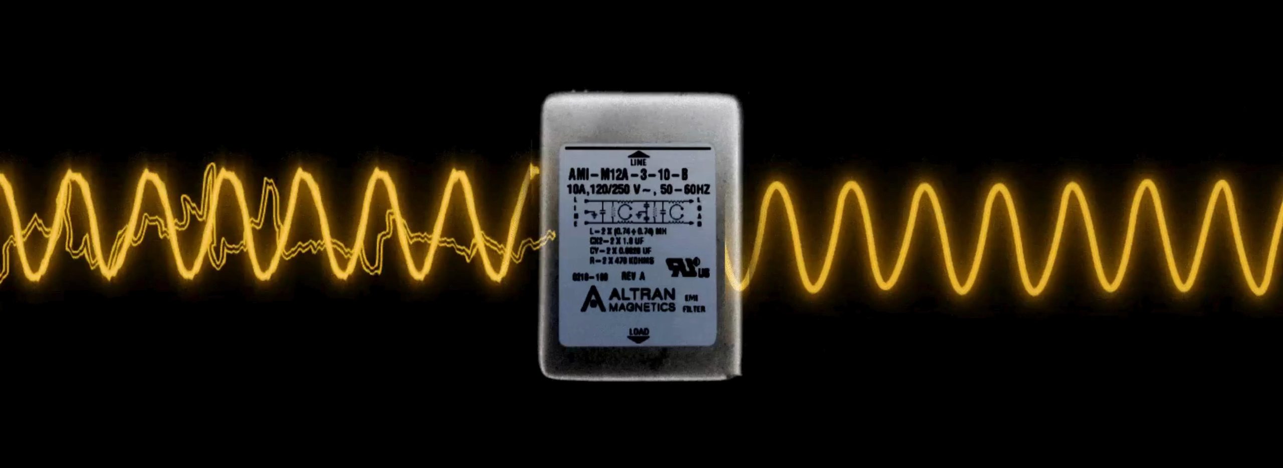
In modern electrical systems, electromagnetic interference (EMI) and radio frequency interference (RFI) represent critical threats to operational stability, signal integrity, and regulatory compliance. Switching power supplies (SMPS), pulse-width modulated (PWM) motor controllers, solar microinverters, and wide-bandgap (SiC/GaN) power converters generate severe conducted noise across electrical supply networks. A **Single Phase EMI Filter** functions as a bi-directional passive low-pass network that prevents high-frequency electromagnetic noise generated within internal electronic circuitry from leaking into the public AC grid (conducted emissions), while simultaneously shielding sensitive equipment from incoming utility voltage spikes, surges, and line transient interference (conducted immunity).
To successfully specify a single phase filter that avoids premature saturation, excessive thermal derating, or unexpected EMC failure during qualification, electrical engineers and procurement directors must evaluate three foundational elements: noise mode distribution, passive impedance mismatching, and dielectric isolation integrity.
Core Engineering Principle: The Dual-Noise Mechanism
Conducted line noise propagates in two distinct modes across single-phase systems (Line, Neutral, Earth Ground):
- Common-Mode (CM) Noise: High-frequency currents that travel in phase on both current-carrying conductors (Line and Neutral) in the same direction and return to the noise source via the protective earth ground conductor. Suppressed primarily via high-permeability toroidal common-mode chokes and Line-to-Ground (Y) safety capacitors.
- Differential-Mode (DM) Noise: Interference currents that travel out on the Line conductor and return on the Neutral conductor in opposite directions. Attenuated through differential-mode inductors (or leakage inductance of CM chokes) and Line-to-Line (X) safety capacitors.
Passive Filter Internal Component Topology
Altran Magnetics designs single phase EMI filters utilizing optimized multi-element passive configurations. The schematic topology balances attenuation performance against physical volume, thermal resistance, and safety leakage limits:
- Common-Mode Chokes (L1, L2): Wound on high-permeability manganese-zinc (MnZn) ferrite or advanced nanocrystalline cores in a coupled, anti-phase winding structure. Operational power frequency currents (50/60 Hz) generate equal and opposite magnetic fluxes that cancel out inside the core, preventing magnetic saturation. High-frequency common-mode noise creates additive magnetic flux, encountering extremely high inductive impedance (Z = 2πfL) that blocks noise transmission.
- Metallized Polypropylene Film Capacitors (X-Capacitors): Connected directly across Line-to-Neutral to shunt high-frequency differential-mode noise currents back to the source. Altran utilizes safety-rated X1 (≤ 4.0 kV impulse) and X2 (≤ 2.5 kV impulse) self-healing capacitors that fail open-circuit under breakdown conditions to prevent destructive short circuits.
- Line-to-Ground Safety Capacitors (Y-Capacitors): Connected from Line-to-Earth and Neutral-to-Earth to divert high-frequency common-mode noise directly into the metallic chassis ground. Y1 and Y2 safety class capacitors undergo stringent dielectric withstand testing. Because Y-capacitor value directly dictates protective earth leakage current, selection involves an active engineering trade-off between attenuation capability and electrical safety limits (e.g., IEC 60601-1 medical compliance).
- Bleeder Resistors (R): High-voltage metal oxide resistors connected across X-capacitors to safely discharge residual electrical potential down to non-hazardous voltage levels (< 60V) within 1 to 5 seconds after AC power disconnect, fulfilling safety guidelines under UL 1283 and EN 60939.
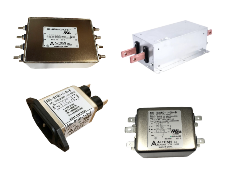
Figure 1: Altran Magnetics compact and industrial single phase EMI line filter family showing multi-stage passive filter construction.
Impedance Mismatching: The Key to Real-World Attenuation
A common pitfall during OEM component sourcing is assuming that a filter’s published 50-ohm insertion loss curve directly predicts performance in the final system. Standard laboratory test setups (CISPR 17) place the filter between a 50-ohm signal generator and a 50-ohm spectrum analyzer spectrum. However, actual electrical AC mains lines exhibit low source impedance (typically 1Ω to 10Ω at low frequencies), while switch-mode power supplies present high dynamic load impedance at power switching frequencies.
Passive filter insertion loss ($IL$) is dictated by the magnitude of impedance mismatch introduced between the source, filter, and load:
$$\text{Maximum Attenuation} \iff \text{High Filter Impedance opposite Low Circuit Impedance}$$
Altran Magnetics application engineers analyze your equipment's specific source and load impedance profiles, selecting optimal inductor-first ($L$-topology) or capacitor-first ($\pi$-topology or $T$-topology) configurations to ensure maximum noise reduction in demanding real-world operating conditions.