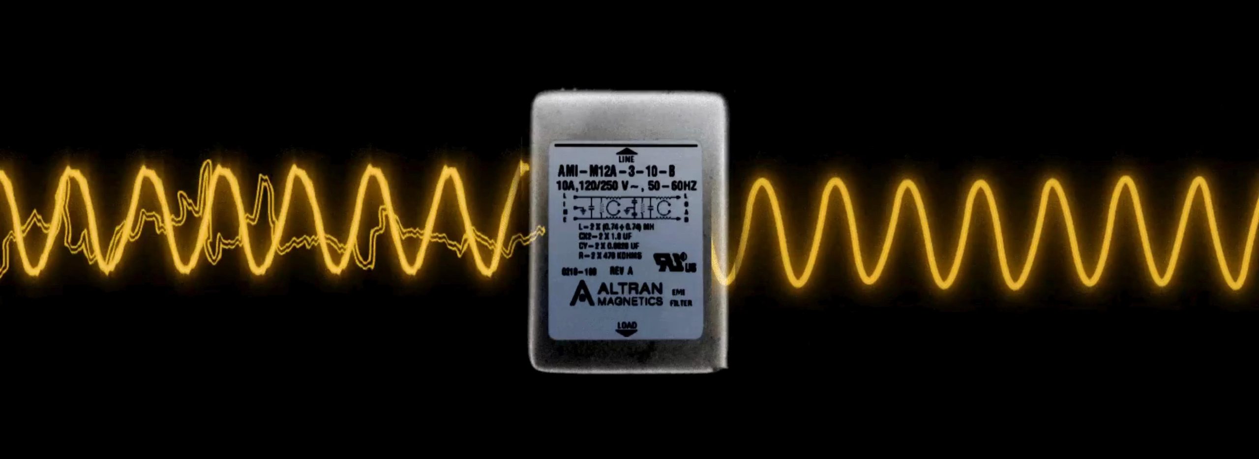
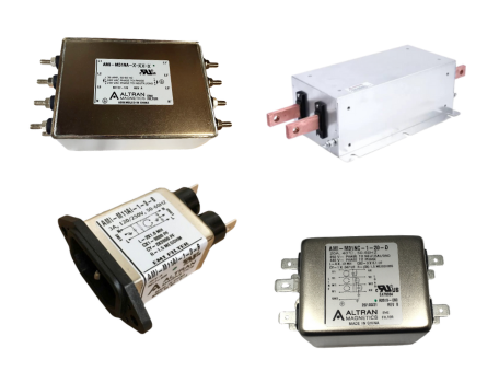
Medical EMI Mitigation Strategy Understanding the Crucial Differences Between Industrial and Medical Grade EMI Filters
For medical OEM design engineers and global procurement directors, specifying an Electromagnetic Interference (EMI) filter for medical electrical equipment requires balancing strict electromagnetic compatibility (EMC) targets with stringent patient safety protocols under IEC 60601-1 and IEC 60601-1-2 (4th Edition).
Unlike standard industrial EMI line filters—which rely heavily on line-to-ground Y-capacitors (typically in the tens of nanofarads range) to shunt common-mode noise directly to earth ground—Medical Grade EMI Filters must drastically restrict or completely eliminate Y-capacitors. This design requirement stems directly from the danger of electrical micro-shocks to patients and operators.
1. Leakage Current Constraints: Earth, Enclosure, and Patient Leakage
In standard commercial power supplies, earth leakage current can easily range from 0.5 mA to 5.0 mA without posing safety risks in grounded factory environments. However, in medical environments—particularly for equipment with direct patient contact—leakage current flowing through the protective earth conductor or chassis can pass directly through a patient's body to ground.
IEC 60601-1 categorizes equipment into three distinct risk tiers based on direct physical application:
- Type B (Body): Non-conductive contact with the patient (e.g., surgical lighting, diagnostic monitors, lab centrifuges). Maximum Earth Leakage Current: <500 µA (Normal Condition).
- Type BF (Body Floating): Conductive contact with the patient's skin (e.g., ECG monitors, ultrasound probes, dialysis equipment, blood warmers). Maximum Earth Leakage Current: <100 µA to <500 µA depending on internal isolation barriers.
- Type CF (Cardiac Floating): Direct physical contact with the patient's heart or bloodstream (e.g., cardiac catheterization devices, artificial heart controllers, infusion pumps). Allowable patient leakage drops to less than 10 µA under Normal Condition and <50 µA under Single Fault Condition.
To ensure that medical devices maintain these ultra-low leakage thresholds, Altran Magnetics designs non-magnetic and ultra-low leakage medical filters where Y-capacitors are either completely removed (creating a zero-leakage line filter) or limited to micro-capacitance values (<100 pF) that guarantee leakage current stays safely under 5 µA to 50 µA at 250 VAC / 60 Hz.
2. Compensating for Reduced Y-Capacitance: Advanced Inductive Topologies
Removing Y-capacitors eliminates high-frequency shunt paths for common-mode electromagnetic noise. If an engineering team simply strips the Y-capacitors out of a standard filter, the device will fail CISPR 11 Class B radiated and conducted emissions testing. To overcome this fundamental engineering tradeoff, Altran Magnetics employs proprietary inductive core compensation techniques:
- Nanocrystalline Core Material Integration: By substituting standard ferrite cores with high-permeability nanocrystalline ribbon cores, our medical chokes deliver up to 3x to 5x higher common-mode impedance per unit volume without increasing physical copper resistance (DCR).
- Multi-Stage Differential & Common-Mode Topologies: We combine high-inductance common-mode chokes with specialized differential-mode inductors and low-ESR X-capacitors across the line lines (L-N), effectively attenuating switching harmonics without generating ground currents.
- Stray Capacitance Minimization Winding Techniques: Winding structures are segmented and precision-layered to minimize internal inter-turn capacitance, preserving high insertion loss past 30 MHz.