
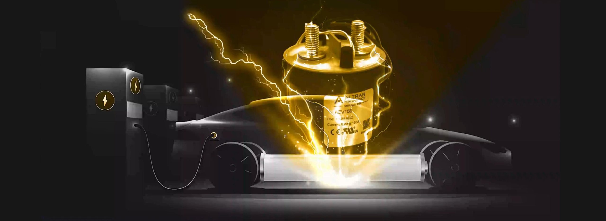
The Physics of High-Voltage Switching in Battery Energy Storage Systems (BESS)
As global energy storage deployments pivot rapidly from 1,000 VDC to high-efficiency 1,500 VDC utility architectures, the engineering challenges surrounding direct current circuit interruption have intensified exponentially. Unlike Alternating Current (AC) networks, which benefit from a natural current zero-crossing point occurring 100 or 120 times per second, Direct Current (DC) maintains uninterrupted plasma ionization during contact separation.
In a high-capacity lithium-ion battery system (incorporating LFP or NMC chemistry), a sudden fault, short-circuit, or emergency trip command requires Energy Storage System DC Contactors to instantly break thousands of amperes of stored electrical energy. If the contactor lacks specialized magnetic arc blowout assemblies or pressurized dielectric gas chambers, the sustained DC arc will quickly vaporize contact materials, leading to catastrophic contact welding, phase-to-ground flashover, or total system fires inside battery enclosures.
Information Gain: Why Standard Industrial Contactors Fail in Energy Storage
Conventional air-break contactors rely on physical contact gap distance to extinguish arcs. In a 1,500 VDC BESS array, an air arc can stretch several inches while remaining conductive at temperatures exceeding 6,000°C. Altran Magnetics solves this through hermetically sealed ceramic or epoxy chambers filled with high-thermal-conductivity gas blends (primarily hydrogen/nitrogen). Hydrogen gas accelerates plasma cooling by orders of magnitude compared to ambient air, extinguishing electric arcs within milliseconds of contact separation.
Key Engineering Factors in BESS DC Contactor Selection
Global procurement directors and system design engineers must evaluate five core electromechanical parameters when specifying DC contactors for battery storage enclosures, power conversion systems (PCS), and battery disconnect units (BDU):
- Continuous Current Thermal Rating ($I_{th}$): The maximum continuous RMS current the contactor terminals can handle without exceeding thermal limits set by UL 60947-4-1 (typically a $65^\circ\text{C}$ temperature rise above ambient).
- Bi-Directional Switching Capability: Battery systems continuously transition between charging (power grid to battery) and discharging (battery to power grid). DC contactors must maintain identical arc-quenching performance regardless of current flow direction.
- Short-Circuit Withstand Current ($I_{cw}$) and Rupture Capacity: The maximum fault current the contactor can carry for a specified duration (e.g., 10 ms to 100 ms) without contacts blowing open due to electromagnetic repulsive forces (Holm forces).
- Coil Power Management (Economizer Efficiency): Continuous hold power consumption across hundreds of battery strings can represent kilowatt-hours of parasitic auxiliary load. Integrated electronic economizers reduce holding current by up to 85%.
- Dielectric Insulation Resistance & Hermetic Seal Integrity: Maintaining $>100\,\text{M}\Omega$ isolation at 1,500 VDC across harsh outdoor operating temperatures ($-40^\circ\text{C}$ to $+85^\circ\text{C}$) over a 20-year design life.
Recommended Energy Storage System DC Contactors
Altran Magnetics engineers high-performance DC contactors tailored specifically to the duty cycles, voltage profiles, and spatial constraints of modern utility, commercial, industrial, and residential energy storage systems.
1,500 VDC / 300A – 500A Contactors
Engineered for utility-scale BESS container arrays, central inverter disconnect units, and heavy industrial battery banks. Features hermetic gas filling, dual permanent magnetic blowouts, and built-in coil economizers for maximum reliability.
Best for: Utility-scale containerized energy storage, 1500V battery management systems (BMS).
1,000 VDC / 100A – 250A Contactors
Ideal for commercial and industrial (C&I) energy storage cabinets, microgrids, and EV fast-charging buffer batteries. Combines compact mounting footprints with robust short-time withstand ratings.
Best for: Factory power backup, solar-plus-storage skid integration, C&I string isolation.
450 VDC / 10A – 50A Contactors
Optimized for residential hybrid solar-storage inverters, pre-charge isolation loops, and low-voltage battery modules. Compact epoxy-sealed design with low coil power draw.
Best for: Pre-charge circuits, home energy storage walls, auxiliary DC distribution boards.
Altran Magnetics Technical Specification Reference Matrix
| Parameter / Specification | Utility BESS Series (1500V) | C&I Storage Series (1000V) | Residential / Pre-Charge (450V) |
|---|---|---|---|
| Maximum Operational Voltage ($U_e$) | 1,500 VDC | 1,000 VDC | 450 VDC – 750 VDC |
| Continuous Current Rating ($I_{th}$) | 300 A / 400 A / 500 A continuous | 100 A / 150 A / 250 A continuous | 10 A / 30 A / 50 A continuous |
| Arc Suppression Technology | Hermetic Ceramic / Hydrogen Gas + Magnets | Epoxy Sealed Gas-Filled Chamber | Enclosed Sealed Contact Structure |
| Bi-Directional Interrupting Rating | Yes (Full rated current both polarities) | Yes (Symmetrical magnetic blowout) | Yes (Standard bi-directional) |
| Peak Fault Breaking Capacity | Up to 3,000 A @ 1,500 VDC (Single break) | Up to 2,000 A @ 1,000 VDC | Up to 500 A @ 450 VDC |
| Coil Voltage Options ($U_s$) | 12 VDC, 24 VDC, 48 VDC (with Economizer) | 12 VDC, 24 VDC PWM option | 12 VDC, 24 VDC standard coil |
| Auxiliary Contact Options | 1 N.O. or 1 N.C. SPST-Aux (Optional) | Optional SPST signal contact | N/A (Compact frame) |
| Operating Ambient Temperature | $-40^\circ\text{C}$ to $+85^\circ\text{C}$ | $-40^\circ\text{C}$ to $+85^\circ\text{C}$ | $-40^\circ\text{C}$ to $+70^\circ\text{C}$ |
| Regulatory Certifications | UL 60947-4-1, cUL, CE, RoHS, REACH | UL 60947-4-1, CE, RoHS | UL Recognized, CE, RoHS |
Future Sourcing & Procurement Trends in Energy Storage DC Contactors
As global energy storage capacity expands at a compound annual growth rate (CAGR) exceeding 25%, procurement managers face tight supply chains, evolving safety mandates (UL 9540A, NFPA 855), and aggressive pressure to lower levelized cost of storage (LCOS). Understanding future component trends is critical to engineering bankable, long-life storage systems.
1. The Shift to High-Density 1,500V DC Architecture
To maximize inverter power density and reduce overall copper cabling cross-sections, battery pack system voltages have migrated from 600V/1000V up to 1,500V nominal (with peak floats approaching 1,750V). Sourcing contactors for 1,500V requires strict attention to creepage distances, dielectric strength, and contact separation speeds. Contactors designed for 1000V applications cannot simply be derated; they require redesigned ceramic arc chambers capable of extinguishing high-voltage plasma before heat damages surrounding plastics.
2. Smart Coil Control and Energy Reduction Demands
Auxiliary power consumption in megawatt-scale BESS installations directly penalizes system round-trip efficiency (RTE). Modern procurement contracts specify contactors equipped with dual-coil internal economizers or integrated pulse-width modulation (PWM) drivers. These units draw high inrush power (e.g., 30W–50W) for 100 milliseconds to guarantee rapid armature closure, then throttle down to holding power as low as 1.5W–3W. Over a 20-year operational life across thousands of installed contactors, this translates into tens of thousands of dollars in energy savings.
3. Enhanced Short-Circuit Withstand Capability (SCCR)
Next-generation lithium battery chemistries (including high-capacity LFP prismatic cells) exhibit extremely low internal impedance, resulting in short-circuit prospective fault currents that can exceed 15,000 to 20,000 Amperes. Procurement teams are moving away from evaluating contactors purely on continuous current, demanding rigorous short-circuit withstand curve validation ($I^2t$ ratings) to ensure contactors remain closed under transient fault surges until high-speed semiconductor fuses isolate the circuit.
4. Supply Chain Localization & Agile Customization
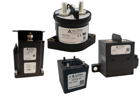
Global OEMs are increasingly avoiding off-the-shelf components with rigid lead times or fixed terminal orientations. Successful procurement strategies rely on agile manufacturing partners capable of supplying customized busbar terminations, specialized auxiliary harness pinouts, custom coil voltages, and co-engineered mounting brackets under revision-controlled OEM part numbers.
Future Development Trends in High-Voltage DC Contactor Technology
Electromechanical components are not static commodity hardware. Continuous innovations in material science, magnetic field simulation, and predictive health monitoring are shaping the next generation of BESS switching equipment.
Advanced Ceramic Braze Enclosures
Transitioning from resin epoxy potting to high-purity alumina ceramic brazed chambers. Ceramic encapsulation allows higher internal gas pressurization, higher thermal resistance, and zero outgassing over 30-year operational lifespans.
3D Lorentz Force Magnetic Blowout Design
Using finite element analysis (FEA) to optimize permanent magnet placement. By directing the Lorentz force ($F = I \times B$) with mathematical precision, electric arcs are driven into cooling fins instantly regardless of current magnitude or vector.
Integrated Contact Resistance Monitoring
Incorporating digital sensing leads to continuously measure micro-ohm contact resistance ($R_{contact}$). System diagnostics can detect micro-welding or contact erosion early, allowing proactive maintenance before catastrophic open-circuit failure.
Engineering Excellence Built in Sterling, Illinois
Altran Magnetics, LLC operates with a singular focus: delivering engineered electrical, electronic, and electromechanical components backed by transparent documentation and direct application engineering assistance. Operating out of our facility at 1741 Industrial Drive, No 14, Sterling, IL 61081, our engineering teams bridge the gap between initial system design and reliable mass production.
When sourcing Energy Storage System DC Contactors from Altran Magnetics, global procurement groups gain access to an agile design framework that prioritizes reliability, compliance evidence, and total system protection.
- Engineering First Direct schematic review, load profile analysis, and environmental modeling before issuing a part quote.
- Quality Rigor 100% functional testing, dielectric withstand verification, and contact resistance screening on every batch.
- Certifications Full compliance with UL, cUL, CSA, CE, RoHS, and REACH requirements, complete with traceable test data.
- Custom OEM Private labelling, custom terminal busbars, specialized lead harnesses, and revision-controlled drawings.
- Continuity Global supply chain buffering, safety stock management, and local US technical support.

Frequently Asked Sourcing & Technical Questions
Answers to critical questions asked by BESS electrical engineers, safety compliance officers, and global purchasing specialists.
AC electrical arcs naturally self-extinguish at zero-voltage crossing points occurring 100 or 120 times per second. DC current does not possess zero-crossing points; once an arc is ignited during contact separation under load, it remains active as long as the voltage differential sustains plasma ionization. Standard AC contactors lack the arc-stretching mechanisms, magnetic blowout permanent magnets, and hermetically sealed gas chambers required to quench high-voltage DC arcs. Utilizing AC contactors in a 1,000V or 1,500V DC energy storage system results in immediate contact welding, housing destruction, and severe fire risk.
Continuous Current Rating ($I_{th}$): Represents the steady-state current the contactor can carry continuously for hours or days without terminal temperatures exceeding safety thresholds specified by UL 60947 standards.
Breaking Capacity (Interrupting Rating): Represents the maximum current magnitude the contactor can physically separate at its rated voltage without catastrophic failure or sustained arcing. For example, a contactor rated at 300A continuous may possess a short-term break capacity of 2,000A at 1,500VDC under emergency fault conditions.
When a contactor breaks a DC circuit under load, current passes through the opening contact gap. By strategically positioning permanent magnets around the arc chamber, the magnetic field creates a Lorentz force ($F = I \times B$) perpendicular to both the arc current vector and magnetic field direction. This force physically pushes the ionizing arc plasma away from the contact tips and into ceramic arc-cooling chutes. In bi-directional contactors, magnet orientation and chute geometry are symmetrical, ensuring that regardless of whether current is flowing into the battery (charging) or out of the battery (discharging), the arc is driven safely into quenching zones.
Electromechanical contactors require high initial coil power to overcome internal spring tension and pull the heavy armature closed rapidly (preventing contact bounce). However, holding the armature closed requires only a fraction of that mechanical force. Coil economizers (either dual-coil mechanical switches or electronic PWM modules) automatically reduce holding power by 70% to 85% after closure. In large containerized BESS installations containing hundreds of contactors, economizers prevent thermal buildup inside battery enclosures and reduce overall parasitic energy consumption.
Contact welding primarily occurs due to two phenomena:
1. Inrush Current During Closure: Closing into capacitive loads without adequate pre-charge circuitry creates massive current spikes, causing micro-arcs that melt contact material and weld contacts together.
2. Holm Repulsive Forces Under Faults: Massive short-circuit currents create electromagnetic forces that push closed contacts apart slightly, creating high-temperature arcs that fuse the contacts when they snap back together.
Altran Magnetics prevents contact welding by utilizing silver-alloy contact materials with high melting points, high contact pressure spring designs, fast armature closure speeds, and co-engineering pre-charge resistor circuits with OEM design teams.
Yes. Custom engineering is a core strength of Altran Magnetics. We regularly engineer modified busbar terminals, custom mounting brackets, auxiliary microswitch lead lengths, specific connector plugs, and unique coil operating voltages (e.g., 12V, 24V, 48V, or 110V DC). Custom configurations are documented under customer-specific part numbers with revision control to guarantee seamless supply continuity.
Altran Magnetics DC contactor series are engineered to meet global industrial and automotive standards including UL 60947-4-1 (Standard for Low-Voltage Switchgear and Controlgear), cUL (Canadian certification), CE Marking (European Conformity), RoHS (Restriction of Hazardous Substances), and REACH. Complete UL file reference numbers, declaration of conformity documents, and material safety compliance sheets are provided with sample deliveries.
Optimize Your BESS Switching System with Altran Magnetics
Partner with our Sterling, Illinois application engineering team to evaluate your battery pack parameters, select the right DC contactor platform, and receive fully documented evaluation samples.