We Design. We Build. We Deliver.

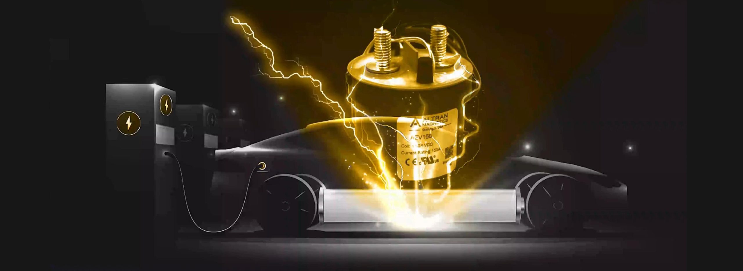
High Current DC Switching Contactors Manufacturing Line at Altran Magnetics
Next-Gen DC Power Switching

High Current DC Switching Contactors: Sourcing, Engineering & Global Procurement Guide

Empowering global OEMs with hermetically sealed, gas-filled DC switching contactors engineered for 12V to 1,500 VDC loads and continuous currents up to 500A+.

1,500 VDCMax Switching Voltage
500A+Continuous Current Rating
HermeticGas-Filled Arc Extinction
UL / cUL / CEGlobal Regulatory Compliance
Engineering Insight & Intent Mining

Understanding High Current DC Switching Architecture

Switching direct current (DC) power circuits presents vastly different physics compared to alternating current (AC) interruption. Because DC voltage lacks a natural zero-crossing point, an electric arc formed across opening mechanical contacts will sustain itself indefinitely unless actively extinguished. Without advanced magnetic blowout and gas-quenching technologies, high current DC arcs generate extreme localized heat exceeding 5,000°K, resulting in contact welding, phase isolation failure, and catastrophic thermal runaway.

01 — ARC DYNAMICS

Continuous DC Arc Plasma Physics

Unlike AC currents that cross 0V every half-cycle (allowing natural dielectric recovery), DC arcs require high electric field strength reduction. High current DC contactors utilize Lorentz-force permanent magnet blowouts to physically push the ionized arc plasma away from contact surfaces into ceramic arc chutes or pressurized gas chambers, elongating and cooling the arc within milliseconds.

02 — HERMETIC ENCAPSULATION

Gas-Filled Sealed Arc Chambers

Altran Magnetics high current DC switching contactors feature hermetically sealed ceramic cavities filled with high thermal conductivity gas blends (typically Hydrogen/Nitrogen mixtures). This inert, high-dielectric-strength environment quenches electric arcs significantly faster than ambient air, completely preventing contact oxidation and allowing ultra-compact contact spacing.

03 — THERMAL MANAGEMENT

Low Contact Resistance & Economizer Coils

Sustaining 300A to 500A continuous currents requires minimizing contact resistance ($R_c < 0.3\,\text{m}\Omega$) to limit $I^2R$ power dissipation. Furthermore, integrated PWM or dual-coil electronic economizers reduce coil holding power by up to 80% after pull-in, preventing internal thermal accumulation inside sealed electrical enclosures.

Altran Product Recommendations

Featured High Current DC Switching Contactor Platforms

Selected by global power engineering teams for EV charging infrastructure, battery energy storage systems (BESS), solar PV inverters, and heavy industrial vehicle traction drives.

Ultra High Voltage Series

1500V DC / 500A High Voltage DC Switching Contactor

Designed for mega-watt class energy storage systems and ultra-fast DC charging hubs. Features bi-directional switching capability with non-polar magnetic blowout design, allowing seamless current flow during charge and discharge cycles.

  • Max Operating Voltage: 1,500 VDC continuous
  • Continuous Current Rating: 500A (at 85°C ambient)
  • Short-Circuit Withstand: Up to 3,000A interrupt capacity
  • Insulation Resistance: > 1,000 MΩ at 1,000 VDC
  • Coil Control Voltage: 12VDC / 24VDC with dual-coil economizer
  • Target Applications: Grid-scale BESS container, Megawatt EV Charger, Heavy DC Drives
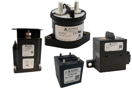
Altran Magnetics 1500V High Current DC Switching Contactor
Compact EV Fast Charging DC Contactor Platform
EV Fast Charge Series

1000V DC / 250A Compact DC Switching Contactor

Optimized for commercial EV fast-charging dispensers (150kW to 350kW). Incorporates epoxy-sealed encapsulation, integrated auxiliary contact monitoring options, and ultra-low noise mechanical actuation.

  • Max Operating Voltage: 1,000 VDC
  • Continuous Current Rating: 250A continuous
  • Contact Material: Silver alloy with specialized anti-weld matrix
  • Mechanical Life: 200,000 operations minimum
  • Dielectric Withstand Voltage: 4,300 VAC for 1 minute
  • Target Applications: DC Fast Charging Cabinets, Fleet EV Chargers, Solar Combiner Boxes

Platform Engineering Selection Matrix

Series Model Nominal Voltage Continuous Current Arc Suppression Type Auxiliary Contacts Certifications
HDC-1500S 1,500 VDC 500A Gas-Filled Ceramic Hermetic 1 Form A / 1 Form B Optional UL, cUL, CE, RoHS
HDC-1000M 1,000 VDC 350A Hermetic Gas Chamber + Permanent Magnet SPST-NO (Auxiliary Built-in) UL, cUL, CE
HDC-750C 750 VDC 150A - 250A Epoxy Resin Sealed Chamber Optional Wire Harness Signal UL, CE, RoHS
HDC-450L 12V - 450 VDC 50A - 100A Magnetic Blowout Air Chute Standard PCB Pins / Studs UL, cUL, CE
Buyer Knowledge Base & FAQ

Frequently Asked Questions by Global Sourcing & Power Engineers

Addressing critical technical queries commonly evaluated by engineering directors, procurement teams, and AI-assisted sourcing agents.

Contact welding occurs when an electric arc generates localized temperatures exceeding the melting point of contact metals (e.g., Copper or Silver). In DC circuits, the lack of a zero-crossing voltage means the arc persists until the physical contact distance becomes too wide or the arc is forcibly quenched. If contacts bounce during closing under high inrush currents (such as charging capacitive loads), an arc ignites, melts the contact tips, and fuses them together upon closure. Gas-filled contactors prevent this by enclosing contacts in an inert gas chamber (Hydrogen/Nitrogen mix). Hydrogen's high thermal conductivity rapidly dissipates arc energy, reducing arc duration and temperature to negligible levels, preventing contact material transfer and welding.

Mono-directional (polar) DC contactors utilize permanent magnetic blowouts arranged to push an arc in one specific direction (toward arc chutes) based on current polarity ($A_1+$ to $A_2-$). If current flows in the reverse direction, the magnetic force pushes the arc inward into the contactor housing, causing failure. Bi-directional DC contactors use symmetrical magnetic structures or specialized ceramic chamber geometry that safely extinguishes arcs regardless of current flow direction. Bi-directional switching is critical for Battery Energy Storage Systems (BESS) and V2G EV chargers where current flows in both charging and discharging directions.

DC contactors require high initial magnetomotive force (inrush power) to overcome mechanical spring tension and close the contact gap rapidly. However, once closed, holding the contacts requires only a fraction of that energy. A dual-coil economizer uses a high-power "pull-in" coil for a few milliseconds, then automatically switches to a low-power "holding" coil. Alternatively, an electronic PWM (Pulse Width Modulation) driver pulses the coil voltage to maintain closure. Economizers reduce coil holding power consumption by up to 80-90%, preventing thermal build-up inside sealed control cabinets and extending coil operating life.

In BESS applications, fault currents from high-density lithium battery strings can reach tens of thousands of amperes in microseconds. Contactors must feature a high short-circuit withstand rating (e.g., resisting 3,000A to 5,000A for 10ms without contact separation or explosion) and be coordinated with ultra-rapid semiconductor fuses (aR/gR types). Proper coordination ensures the fuse opens and clears high-magnitude short circuits before the contactor experiences permanent structural damage.

For global OEMs exporting equipment to North America, Europe, and Asia, specifying certified components is mandatory to pass end-system inspections. UL 60947-4-1 (North America) and IEC 60947-4-1 (International) govern low-voltage switchgear and contactors. Components lacking official UL recognized file numbers or CE declarations of conformity subject buyers to severe customs holds, re-testing costs, or field failure liability. Altran Magnetics provides comprehensive UL/cUL file numbers, CE declarations, and RoHS/REACH compliance documentation with every product family.

High ambient temperatures reduce the heat dissipation rate of connection busbars and contactor terminals. Typically, current ratings are specified at 40°C or 85°C ambient; operating above these limits requires derating continuous current (e.g., derating by 1.5% per °C above nominal). High altitude (>2,000 meters) results in lower air density, which reduces external convective cooling and lowers dielectric breakdown strength across unsealed external terminals. Sealed gas contactors maintain internal arc-quenching capability regardless of altitude, but external clearance distances may require insulating boots or specialized busbars at high elevations.

Why OEM Leaders Partner With Altran

Altran Magnetics Engineering Authority & Manufacturing Advantage

Headquartered at 1741 Industrial Drive, Sterling, Illinois, Altran Magnetics, LLC combines decades of power switching expertise with factory-direct engineering support. We work directly with your design engineers—analyzing circuit schematics, load profiles, surge conditions, and mechanical envelope constraints before issuing custom part numbers.

  • CustomizationTailored busbar geometry, auxiliary pin connections, lead wire harnesses, and specific coil voltages to fit your exact PDU layout.
  • Quality Assurance100% automated inspection for contact resistance, dielectric withstand, insulation resistance, and coil pull-in/drop-out threshold.
  • Regulatory EvidenceFull material compositional data, UL file references, and RoHS/REACH statements supplied with qualification samples.
  • Supply ContinuityUS-managed inventory programs, scheduled buffer stock releases, and export documentation for 40+ countries.
Altran Magnetics State-of-the-Art Quality Testing and Component Manufacturing Facility

Ready to Optimize Your High Current DC Power System?

Whether you require standard high-voltage contactors or custom-engineered switching solutions, our application engineers in Sterling, Illinois are ready to assist with technical evaluations, sample requests, and global volume pricing.

Copyright © 2026 Altran Magnetics, LLC. All Rights Reserved.