We Design. We Build. We Deliver.
Engineered for extreme duty cycles, ambient temperature resilience, and minimal contact resistance in smart grid, HVAC, solar inverter, and EV charging platforms.
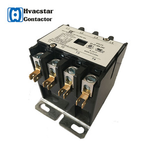
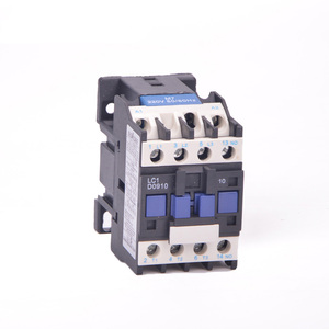
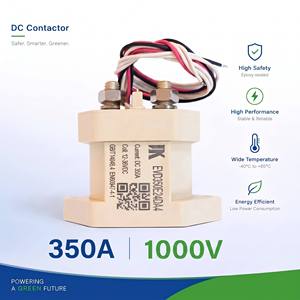
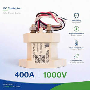
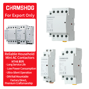
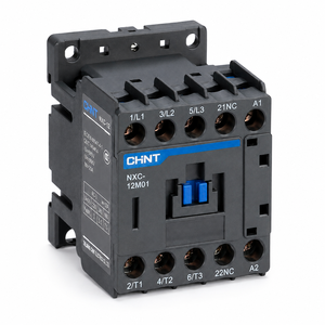
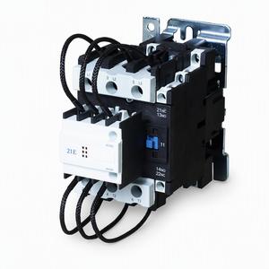
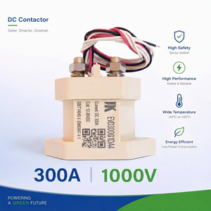
In high-density power electronics, Printed Circuit Board (PCB) relays serve as critical electromechanical interfaces between low-voltage digital microcontrollers and high-power AC/DC loads. Selecting an OEM/ODM relay supplier requires a granular understanding of contact metallurgy, magnetic circuit efficiency, insulation clearance distance, and transient voltage suppression.
As industrial automation, EV charging architectures, and renewable energy storage systems evolve toward higher power densities, traditional switching designs face severe operational constraints. This white paper outlines the core engineering parameters, customization options, and quality verification methodologies required for reliable long-term deployment.
The choice of contact material dictates electrical endurance, resistance to contact welding, and thermal dissipation performance under high-inrush conditions (e.g., capacitive loads, lamp loads, or motor startup currents):
| Contact Alloy Material | Typical Current Rating | Peak Inrush Resistance | Primary Application Profile |
|---|---|---|---|
| AgSnO2 (Silver Tin Oxide) | 10A – 40A | Up to 120A (20ms) | Smart Metering, Solar Inverters, HVAC Definite Purpose, EVSE |
| AgNi (Silver Nickel) | 3A – 16A | Medium (up to 30A) | Industrial Automation, PLC Outputs, Home Automation Switches |
| AgNi + Au Flash | 10mA – 2A | Low (Signal level) | Medical Instrumentation, Telecommunications, Low-Voltage Logic Interfacing |
Modern power electronics operating on 230V/400V mains grids must strictly adhere to isolation standards outlined in IEC 61810-1 and IEC 60664-1. Creepage distance (the shortest path along the surface of the insulating material) and clearance distance (the shortest path through air) prevent dielectric breakdown and flashover events during lightning surges or inductive load spikes.
Our custom OEM/ODM PCB relays incorporate molded coil bobbins and elevated contact chambers that achieve:
Continuous coil energization generates internal ohmic heat ($P = I^2 R$), raising ambient temperatures within tightly sealed control cabinets. To optimize energy consumption and minimize thermal stress, our OEM custom engineering team offers specialized coil options:
Standard off-the-shelf relays often require compromises in layout, thermals, or pin configuration. As a dedicated OEM/ODM manufacturer, Altran Magnetics provides end-to-end design modifications directly aligned with your custom PCB footprint and system requirements.

Procurement strategy is transitioning from lowest-unit-cost evaluation to long-term reliability risk mitigation and global regulatory alignment.
With the rise of 800V EV architectures, battery energy storage systems (BESS), and DC microgrids, PCB relays must safely break high-voltage DC arcs. Advanced gas-filled (Hermetically Sealed) and magnetic blow-out relay designs prevent sustained arcing, avoiding contact catastrophic erosion.
Industrial IoT sensors and smart home actuators demand smaller footprints without sacrificing power handling. Next-generation narrow-profile power relays achieve 16A switching capacity within a package width under 10mm, freeing up valuable PCB board space.
Global environmental mandates continue to tighten. Sourcing strategies require strict adherence to RoHS 3, REACH SVHC, and emerging PFAS-free insulation material guidelines, ensuring products pass international customs smoothly and maintain market compliance.
Combining US engineering oversight from Sterling, Illinois, with scalable global manufacturing capabilities to eliminate supply chain vulnerabilities.
We do not just ship part numbers. Our design engineers review your load profiles, ambient thermal limits, duty cycles, and creepage requirements before issuing a production quote—preventing field failures before tooling begins.
Every single relay batch undergoes automated 100% End-of-Line testing for coil resistance, pull-in/drop-out voltage thresholds, contact resistance, dielectric strength, and contact operation timing.
Complete lot traceability tied to raw material heat numbers and assembly station timestamps. Our products carry UL, cUL, CE, VDE, and CSA agency approvals with published safety file records.
Detailed technical responses to common questions raised by component engineers, buyers, and global quality auditors.
RT II (Flux-tight): Designed to prevent liquid solder flux from entering the relay housing during automated wave soldering. It allows internal pressure venting during operation, ideal for standard industrial environments.
RT III (Wash-tight / Sealed): Fully sealed relays capable of withstanding automated aqueous or chemical washing processes after soldering without fluid ingress. Essential for applications involving conformal coating, encapsulation/potting, or outdoor exposure in high-humidity environments.
Capacitive inrush currents (commonly seen in LED drivers, switching power supplies, and solar inverters) generate short-duration current spikes up to 50 times nominal current. We address this using high-density AgSnO2 contact materials paired with tungsten pre-contacts or optimized contact spring dynamics that reduce contact bounce to < 2ms.
Yes. For battery-powered IoT devices and remote telematics, we offer custom high-sensitivity coils (down to 150mW) or single/dual-coil latching (bistable) mechanisms. Latching relays only require a 50ms voltage pulse to change contact state, reducing steady-state power draw to 0W.
All customized and standard relay families ship with comprehensive compliance documentation packages, including UL/cUL Recognized component files (UL 508 / IEC 61810), CE Declarations of Conformity, VDE certification reports, RoHS 3 material composition declarations, and REACH SVHC compliance data sheets.
Standard engineering modifications (custom terminal bends, specialized coil winding voltages) are typically sampled within 2 to 3 weeks. Complete custom ODM housing development, terminal stamping tooling, and full UL qualification testing generally require 6 to 10 weeks depending on complexity.
Speak directly with our application engineering team in Sterling, Illinois. Receive tailored thermal assessments, component cross-references, and sample delivery for your build schedules.