We Design. We Build. We Deliver.
Explore our flagship OEM component platforms designed for heavy industrial automation, HVAC/R systems, EV charging networks, and renewable battery disconnect modules.
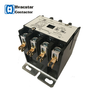
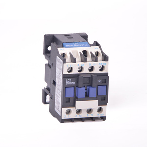
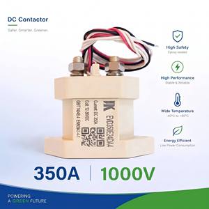
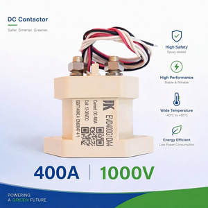
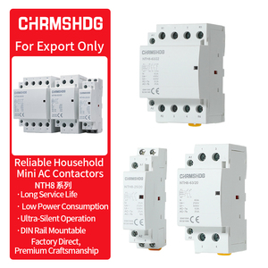
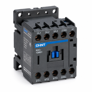
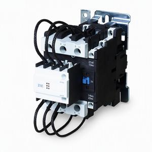
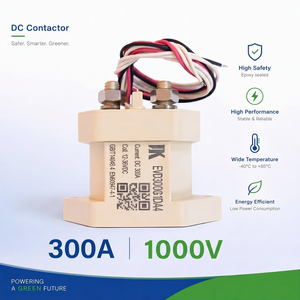
Modern industrial power electronics demand extreme switching reliability, zero acoustic noise, and immunity to harsh electromagnetic interference (EMI). As a dedicated Custom OEM Solid State Relay (SSR) Manufacturer & Exporters operating under rigorous engineering governance, our product lines bridge the gap between high-frequency signal processing and heavy-duty load regulation.
Solid State Relays utilize semiconductor switching components—primarily SCRs (Silicon Controlled Rectifiers), Triacs, Power MOSFETs, or insulated-gate bipolar transistors (IGBTs)—optically coupled to control inputs. Unlike traditional electromechanical relays (EMRs), SSRs eliminate all moving mechanical contacts. This optical isolation barrier guarantees complete galvanic separation between sensitive microcontroller control loops and high-voltage AC/DC industrial mains.
Choosing the correct SSR switching architecture is paramount to avoiding excessive total harmonic distortion (THD), inrush current spikes, and catastrophic thermal runaway. Our custom OEM engineering capabilities encompass three distinct operational modes:
From complete customization of internal substrate layouts to private-label assembly, our Sterling, Illinois design mindset delivers audit-proof reliability.
We utilize pure alumina ceramic substrates with Direct-Bonded Copper technology, delivering exceptional thermal conductivity, high mechanical strength, and $4,000\text{V}_\text{RMS}$ isolation breakdown endurance.
Integrated metal-oxide varistors (MOVs) and advanced RC snubber networks protect internal antiparallel SCR outputs against voltage spikes ($dv/dt$ overshoot exceeding $1,000\text{ V/}\mu\text{s}$).
All custom product lines are designed to satisfy international standards including UL 508, cUL, CE, CSA, and RoHS/REACH compliance. Full documentation packages ship with samples.
When selecting power control switches for long-life industrial machinery, technical teams must weigh life-cycle operating costs against initial bill-of-materials (BOM) investment. Below is a comprehensive engineering comparison table:
| Performance Characteristic | Solid State Relays (SSR) | Electromechanical Contactors (EMR) | Engineering Impact |
|---|---|---|---|
| Operating Life Span | > 100 Million Cycles | 1 Million to 3 Million Cycles | Zero maintenance downtime in high-duty cycle applications. |
| Switching Speed | Microseconds (< 100 µs) | 15 to 50 Milliseconds | Enables fine-grained PWM PID temperature control loops. |
| Acoustic Noise | Completely Silent (0 dB) | Audible Click / Contact Chattering | Essential for medical equipment, lab devices, & office HVAC. |
| Contact Arcing & Bounce | Zero Arcing / No Bounce | Severe Arcing Under Inductive Load | Eliminates explosive spark risk in hazardous chemical zones. |
| Thermal Management Needs | Requires Heatsink ($1.0 - 1.2\text{ W/A}$) | Minimal Thermal Losses at Terminals | SSRs require engineered heatsinking & thermal interface pad. |
| Vibration Immunity | 100% Solid Solid-State Shell | Prone to Contact Bounce under Shock | Superior for railway, mining, and off-highway transportation. |
The transition from silicon-based thyristors to Wide-Bandgap (WBG) materials such as Silicon Carbide (SiC) and Gallium Nitride (GaN) is revolutionizing SSR architecture. SiC MOSFET solid-state relays operate at drastically higher temperatures, offer ultra-low internal resistance ($R_{DS(on)}$ reduction up to 60%), and minimize heat dissipation footprint requirements by more than half. As an export leader, our OEM R&D division is already integrating SiC dies into high-voltage DC switching disconnects for solar microgrids and DC fast charging networks.
Next-generation industrial SSRs are evolving from passive components into intelligent nodes. By incorporating micro-sensors into the epoxy potting compound, modern smart SSRs continuously monitor terminal temperatures, load current RMS values, and dielectric leakage current. Data is communicated via IO-Link or Modbus back to the central PLC, enabling predictive maintenance alerts days before a thermal heatsink fan fails or a heater wire breaks.
Global procurement teams face increasing pressure to mitigate lead time risks and geopolitical supply disruption. OEMs are standardizing on universal multi-voltage input SSR control circuits (e.g., 4-32VDC and 90-280VAC in a single universal footprint) and modular DIN-rail hockey-puck form factors. This consolidation minimizes raw inventory SKU counts while assuring seamless drop-in replacements across regional manufacturing hubs in North America, Europe, and Asia-Pacific.
Clear, uncompromising answers to critical engineering, manufacturing, and procurement inquiries.
Proper thermal management is the single most critical factor in SSR longevity. As a general rule, a single-phase AC solid-state relay generates approximately 1 to 1.2 Watts of heat per Ampere of continuous load current. The maximum allowable thermal resistance of the heatsink ($R_{th,Heatsink}$) is calculated using the formula:
Rth,Heatsink = [(Tj,max - Ta) / Power Loss] - Rth,j-c - Rth,c-s
Where $T_{j,max}$ is maximum junction temperature (typically 125°C), $T_a$ is maximum ambient temperature inside the enclosure, $R_{th,j-c}$ is internal junction-to-case thermal resistance, and $R_{th,c-s}$ is thermal pad resistance. Our application engineering team provides free thermal simulation curves and customized pre-attached heatsink options for high-volume OEM orders.
Zero-Cross SSRs turn ON only when the sine wave AC voltage reaches zero volts. This minimizes electrical noise (EMI/RFI) and inrush current surges, making them the optimal choice for resistive loads such as heating elements and lamps. Random Turn-On SSRs switch ON immediately upon signal trigger. They are required when implementing phase-angle control for lamp dimming, speed control of AC motors, or when switching highly inductive loads with phase shifts (such as heavy transformers or solenoids).
Semiconductor chips inside SSRs have lower thermal mass than copper contacts in mechanical relays, making them vulnerable to rapid thermal destruction during direct short circuits. Standard thermal-magnetic circuit breakers are too slow to protect solid-state outputs. Engineers must specify ultra-fast semiconductor fuses (rated with an $I^2t$ thermal capacity lower than the maximum rated $I^2t$ fuse rating of the SSR semiconductor die).
Yes. Custom engineering is our core strength. We routinely manufacture specialized terminal options (screw clamp, push-in spring terminal, faston quick-connect, or direct PCB solder pins), custom potted epoxy enclosures, special coil voltages, integrated MOV snubbers, and custom private-label laser etching. All custom builds are tracked under revision-controlled engineering drawings.
Every production batch undergoes 100% automated end-of-line functional testing, including isolation dielectric withstand testing ($V_{ISO}$), zero-cross firing voltage check, off-state leakage current measurement, and turn-on response time verification. OEM shipments include standard Certificates of Conformance (CoC), RoHS 3 and REACH compliance statements, material composition data, and direct UL/cUL file reference numbers.
Standard prototype samples for catalog SSRs and contactors are dispatched within 3 to 5 business days. Custom engineering modifications (such as specialized mounting brackets, custom wiring harnesses, or targeted snubber tuning) generally take 2 to 3 weeks for fully qualified 3D-printed/machined samples. Full volume production runs typically ship within 4 to 6 weeks, with safety-stock buffering available for scheduled annual blanket purchase orders.
Whether you require a custom high-current zero-cross SSR, a custom DC fast-charging contactor, or an obsolete competitor cross-reference, our engineering team is ready to analyze your schematics.