We Design. We Build. We Deliver.
DIN Rail Solid State Relays are compact switching devices designed to control electrical loads from a standard DIN rail. They fit neatly inside control cabinets, beside circuit breakers, contactors, and terminal blocks. Unlike electromechanical relays, they use semiconductor components instead of moving contacts. This design enables silent operation, rapid switching, and reduced mechanical wear.
Industrial automation engineer and relay specialist Steve Jobs once said, “Design is not just what it looks like and feels like. Design is how it works.” Although he was not a relay manufacturer, this principle applies clearly here. A well-designed DIN Rail Solid State Relay must manage heat, current, switching frequency, and electrical noise—not merely occupy less panel space.
Inside the enclosure, an optocoupler separates the control circuit from the load circuit. A zero-cross AC model can reduce electrical interference when switching heaters. A DC-output version may control valves, lamps, solenoids, or small motors. However, “solid state” does not mean failure-proof. Leakage current can keep sensitive loads faintly energized. Heat sinks may become necessary under continuous load. The relay’s rated current can also fall sharply inside a hot cabinet.
This article will explain how DIN Rail Solid State Relays work, where they perform best, and where their limitations become important. The practical details matter. A relay that looks correctly sized on paper may still overheat after hours of operation. That is an easy mistake to make. Clear selection rules, wiring checks, and realistic derating will help readers choose a safer and more dependable solution.
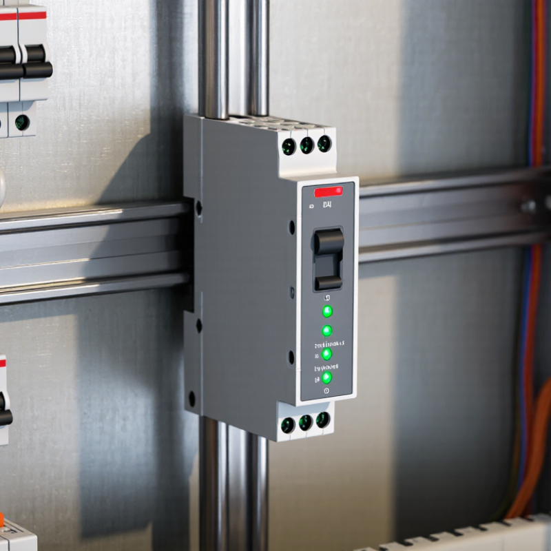
A DIN rail solid state relay is an electronic switching device mounted on a standard DIN rail inside a control cabinet. It uses semiconductor components instead of mechanical contacts to control a load. The input circuit receives a low-power control signal, often from a PLC or temperature controller. The output circuit then switches a separate AC or DC load.
Its core function is electrical isolation and dependable switching. An optically isolated input helps protect control equipment from load-side voltage. Since there are no moving contacts, the relay operates silently and avoids contact wear. Zero-crossing models can reduce electrical noise when switching AC heaters. Random-turn-on models may suit applications requiring tighter timing. The difference matters.
In practical panel work, correct sizing is more important than the relay label. A 10-amp load may require a higher-rated relay after temperature, duty cycle, and inrush current are considered. Heat is the hidden problem. A relay can feel warm while operating normally, yet excessive heat can shorten its service life. A heat sink or ventilation may be necessary. Check the datasheet.
DC loads require special attention because many solid state relays cannot switch both current types. Output leakage current can also keep a small lamp faintly glowing after shutdown. This detail is easy to miss. Wiring errors, poor terminal tightening, and incorrect fuse selection remain common weaknesses. A careful installer verifies voltage, current, polarity, and ambient temperature before energizing the cabinet. Even experienced technicians sometimes underestimate inrush current.
What Are DIN Rail Solid State Relays?
Main Components and Internal Switching Process
A DIN rail solid state relay is a compact electronic switch for control cabinets. Its housing clips onto a standard mounting rail. Unlike an electromechanical relay, it has no moving contacts to wear out. The real engineering story is inside.
The input terminals receive a low-power control signal. An optocoupler transfers that signal across an isolation barrier. This separation protects the control circuit from the load side. A driver circuit then activates the power semiconductor. AC models commonly use triacs or thyristors, while DC models often use MOSFETs. A heat-spreading base helps move thermal energy away from the switching device. Some designs also include snubber components to reduce voltage spikes.
When the input voltage reaches its operating level, the control circuit sends a drive signal to the semiconductor. In zero-cross AC designs, switching begins near the voltage waveform’s zero point. This can reduce electrical noise and inrush stress. Phase-controlled models switch at another point, allowing more precise power control. Turning off also depends on the circuit. AC devices may stop conducting near the next current zero, while DC devices require the drive signal to be removed.
During a practical panel check, I inspect terminal labels, wire torque, and ventilation space. A relay may feel cool yet operate above its rated temperature. That can mislead. Heat remains a major concern. Load current, ambient temperature, switching frequency, and heat-sink contact all affect service life. Installation records should include these details, even when the relay appears simple.
| Process Stage / Component | Primary Function | Typical Electrical Data | Internal Switching Behavior |
|---|---|---|---|
| Control Input Terminals | Receive the command signal from a controller, PLC, thermostat, or other automation device. | Common input ranges include 3–32 V DC or 4–32 V DC; some versions use 90–280 V AC. | The applied input voltage supplies current to the internal input LED or control circuit. |
| Input Current-Limiting Circuit | Controls the current entering the input stage and protects the LED or electronic driver. | Typical DC input current is approximately 5–20 mA, depending on the relay design and input voltage. | The circuit converts the external control voltage into a controlled forward current for the optical isolator. |
| Optical Isolator | Provides galvanic isolation between the low-voltage control circuit and the load-switching circuit. | Isolation ratings commonly range from approximately 2.5 kVrms to 5 kVrms, depending on construction. | The input LED emits light to activate a phototriac, photovoltaic coupler, or other isolated semiconductor driver. |
| Control and Trigger Circuit | Shapes the isolated signal and determines when the output semiconductor is permitted to conduct. | May include trigger circuitry, gate-drive components, voltage detection, and transient protection. | In a zero-cross design, output conduction is enabled near the AC voltage zero crossing to reduce inrush and electromagnetic interference. |
| Power Semiconductor | Performs the actual electronic switching of the load circuit without mechanical contacts. | AC versions commonly use triacs or back-to-back thyristors; DC versions commonly use MOSFETs. Typical load ratings range from a few amperes to tens of amperes. | When triggered, the semiconductor presents a low-resistance path to the load. When disabled, it blocks most of the circuit voltage. |
| AC Zero-Cross Detector | Synchronizes switching with the AC waveform. | Usually used for resistive, capacitive, and some inductive AC loads; it does not provide proportional phase-angle control. | The relay waits until the AC voltage approaches zero before turning on. It normally turns off when the load current naturally falls below the holding current. |
| Random-Turn-On Circuit | Allows the AC output to switch at nearly any point in the waveform. | Used when fast response or phase-angle control is required; it can produce higher switching transients than zero-cross designs. | The output semiconductor begins conducting shortly after the input command reaches the trigger threshold, regardless of the instantaneous AC voltage. |
| Snubber Network | Limits rapid voltage changes and helps protect the output semiconductor from inductive transients. | Often consists of a resistor and capacitor connected across the output switching device. | Absorbs or slows transient energy during switching, although it can contribute to a small off-state leakage current. |
| Output Terminals | Connect the solid state relay in series with the AC or DC load circuit. | Typical AC output ranges include 24–280 V AC or 24–480 V AC; DC models commonly cover 5–60 V DC or higher, depending on design. | The terminals carry load current through the semiconductor rather than through moving contacts. |
| Thermal Path and Heat Sink | Transfers heat generated by semiconductor conduction losses to the surrounding air or an external heat sink. | Typical on-state voltage drop for AC semiconductor outputs is about 1–1.6 V, creating heat proportional to load current. | As current increases, power dissipation rises. Adequate ventilation, spacing, and heat sinking may be required for continuous operation. |
| Protective Components | Reduce damage from overvoltage, surges, reverse polarity, and excessive temperature. | May include varistors, transient-voltage suppressors, fuses, reverse-polarity protection, and thermal protection. | Protection components clamp or interrupt abnormal electrical conditions before they exceed the semiconductor’s safe operating limits. |
| DIN Rail Housing and Mounting Clip | Provides electrical insulation, mechanical protection, and quick installation on a standard mounting rail. | Commonly designed for 35 mm top-hat DIN rail systems; housing width varies by current rating and functions. | The enclosure does not perform the switching operation but supports safe spacing, terminal access, and panel organization. |
| Off-State Leakage | Describes the small current that can flow through the output when the relay is commanded off. | Often specified in the microampere to milliampere range, depending on output voltage, snubber design, and relay type. | The output is electrically blocking but not an ideal open circuit. High-impedance loads may require a parallel bleeder resistor or load device. |
| Complete Switching Sequence | Describes the signal path from the control command to load energization. | Typical response times are from fractions of a millisecond to several milliseconds, depending on the circuit and switching mode. | Control signal applied → input current flows → isolator emits light → trigger circuit activates → power semiconductor conducts → load receives power. When the signal is removed, the semiconductor stops conducting at the appropriate turn-off condition. |
DIN rail solid state relays switch electrical loads without mechanical contacts. Common types include AC-output, DC-output, AC-to-AC, and DC-to-DC models. AC versions often use zero-cross switching to reduce electrical noise. Random-fire versions suit phase control, heaters, and motor applications. DC versions usually switch faster and work well with valves, lamps, and small actuators.
Ratings need careful reading. Check the load voltage, continuous current, surge current, leakage current, and required heat dissipation. A relay marked 25 A may not safely carry 25 A inside a crowded enclosure. Ambient temperature, switching frequency, and the manufacturer’s derating curve matter. IEC 62314:2018 identifies solid state relay performance considerations, while IEC 60947-1 supports broader low-voltage equipment requirements.
That shortcut fails. Real panels are warmer than test benches.
Control signals vary by application. Common inputs include 3–32 V DC, 4–32 V DC, and 90–280 V AC. Some industrial models accept 0–10 V or 4–20 mA signals through internal conditioning. Confirm input polarity, minimum activation current, and isolation voltage.
The IEA’s Electricity 2024 report expects global electricity demand to grow by about 3.4% annually through 2026, increasing pressure on efficient switching and thermal design. A 2024 industrial automation market report also identifies modular, DIN-mounted control hardware as a growing adoption area.
These figures guide planning, not final sizing. Verify every load experimentally.
A DIN rail solid state relay (SSR) mounts inside an electrical cabinet and switches loads without mechanical contacts. Its compact housing makes installation tidy, but heat management remains critical. Clip the relay firmly onto a compatible rail. Check that the rail is clean, straight, and securely grounded when required by the enclosure design. Always isolate power before touching terminals, even when the control circuit appears inactive.
Read the relay’s terminal markings carefully. Confirm whether the input requires AC or DC control voltage. Match the output type to the load, because an AC SSR cannot replace a DC switching device. Use correctly rated conductors, ferrules where appropriate, and the manufacturer’s specified tightening torque. Protect the load circuit with suitable overcurrent protection. An SSR may fail short, not open. That detail deserves attention.
Tips: Leave airflow around heat-producing relays. Check the load current at its real operating temperature, not only on paper. Measure leakage voltage across the load when switched off, especially with lamps, valves, or electronic power supplies. A small voltage can remain. Use a meter and verify the result. One common mistake is trusting a cool cabinet during testing; continuous switching may create heat later. I would recheck spacing, terminal tightness, and enclosure temperature after several hours of operation. If the circuit controls hazardous voltage, have a qualified electrician inspect the installation.
What Are DIN Rail Solid State Relays?
Applications, Benefits, and Common Limitations
DIN rail solid state relays (SSRs) mount directly inside control cabinets and switch loads without mechanical contacts. They commonly control heaters, pumps, lighting, HVAC valves, and small motors. A 2024 market report by Grand View Research estimated the global solid state relay market at about USD 1.4 billion in 2023, with continued growth expected through 2030. This reflects wider demand for compact, fast, and low-maintenance switching equipment.
In field applications, the main benefit is silent operation. There is no contact bounce, arcing, or mechanical wear. Switching also occurs quickly, which helps temperature controllers maintain steadier output. Zero-crossing models can reduce electrical noise when switching resistive loads. However, DIN rail SSRs still generate heat. At higher currents, engineers must provide cabinet airflow, suitable spacing, and careful derating. A relay rated for 25 A may require less current in a warm enclosure.
Leakage current is another practical limitation. A connected lamp or valve may remain faintly energized after switching off. Some loads also need snubber circuits or surge protection. In my panel work, incorrect heat calculations have caused more trouble than relay failure. That detail deserves attention. Selection should follow the load type, switching frequency, ambient temperature, and applicable requirements in IEC 62314. SSRs are efficient tools, but they are not magic switches.
DIN rail solid state relays are compact, non-mechanical switching devices designed for mounting on standard DIN rails. They are commonly used for heaters, lighting, pumps, fans, valves, and other automated control loads.
Typical response-time ranges shown in milliseconds. Actual performance depends on load type, control voltage, switching mode, frequency, temperature, and the specific relay design.
Frequent switching of heaters, lamps, solenoid valves, fans, pumps, and PLC-controlled loads.
Fast and silent operation, no mechanical contact wear, long electrical life, and reduced electrical arcing.
Leakage current, heat generation, voltage drop, thermal derating, and possible failure in a shorted-on state.
It is an electronic switch mounted inside a control cabinet. It uses semiconductor components, not mechanical contacts. A low-power signal controls a separate AC or DC load. Operation is silent.
AC-output models switch heaters, lamps, and other alternating-current loads. DC-output models suit valves, lamps, and small actuators. Check the output type carefully. AC and DC are not interchangeable.
Zero-crossing models switch AC near the voltage zero point. They can reduce electrical noise from heater switching. Random-turn-on models switch at a chosen point in the waveform. Timing matters here.
Check load voltage, continuous current, surge current, and leakage current. A 10-amp load may need a higher-rated relay. Inrush current can briefly exceed normal operating current. The printed rating is not the whole answer.
Heat can shorten relay life, especially inside crowded cabinets. A 25-amp rating may not apply at high ambient temperature. Use the derating curve and check airflow. A heat sink may be necessary. Warm is not always dangerous.
Common inputs include 3–32 V DC and 90–280 V AC. Some models accept 0–10 V or 4–20 mA signals. Confirm polarity, activation current, and isolation voltage. A similar-looking input may still be unsuitable.
DC loads require matching output polarity and voltage. Some relays switch only AC or only DC. Output leakage current may keep a small lamp faintly glowing. That detail is easy to miss.
Verify voltage, current, polarity, wiring, terminal tightness, and ambient temperature. Select suitable fuses and inspect the load’s inrush current. Check ventilation around the relay. I might overlook one detail without a checklist.
DIN Rail Solid State Relays are compact, electronically controlled switching devices designed for mounting on standard DIN rails inside control cabinets. Unlike mechanical relays, they use semiconductor components such as optocouplers, power transistors, or thyristors to switch electrical loads without physical contacts. Their main elements typically include an input control circuit, isolation barrier, switching device, heat dissipation structure, and protective components. Depending on the design, they can handle AC or DC loads and accept control signals such as low-voltage DC, AC, or variable industrial inputs.
Proper installation requires selecting suitable voltage, current, switching mode, and heat-management capacity. Wiring should follow the relay’s input and output terminals, with correct polarity for DC circuits and appropriate protection against overloads, surges, and excessive temperature. DIN Rail Solid State Relays are widely used in automation, heating systems, lighting control, motor interfaces, and process equipment because they provide fast, silent, durable, and frequent switching. However, they may generate heat, experience leakage current, and require careful load compatibility and thermal planning.

Copyright © 2026 Altran Magnetics, LLC. All Rights Reserved.