We Design. We Build. We Deliver.
Industrial Solid State Relays can look simple on a catalog page: a current rating, a voltage range, and a compact case. In a real control cabinet, the choice is less tidy. A relay switching a resistive heater faces different demands from one driving a motor, solenoid, or transformer. Load type, switching frequency, ambient temperature, heat-sink quality, and leakage current all matter. Small details can become expensive surprises.
Power-electronics researcher Dr. Robert W. Erickson is a relevant technical reference for understanding switching devices and their behavior in circuits. His published work supports a broader engineering lesson: components must be evaluated in their operating conditions, not by headline specifications alone. No verified, topic-specific quotation from him about Industrial Solid State Relays was provided, so this guide will not put invented words in his mouth. A useful selection rule is: “Match the relay to the load, switching duty, and thermal path.”
This 2026 guide examines the decisions that shape reliable relay selection, from AC or DC output types to load-current margins, zero-crossing behavior, and protection needs. It also considers practical installation details, such as a warm enclosure, crowded DIN rails, and the airflow around a heat sink. Datasheets deserve careful reading. Yet they do not replace checks against the actual load profile. Even a well-rated relay can fail early if heat accumulates or inrush current is overlooked. Some applications remain ambiguous until measured. That uncertainty deserves attention, not a guess.
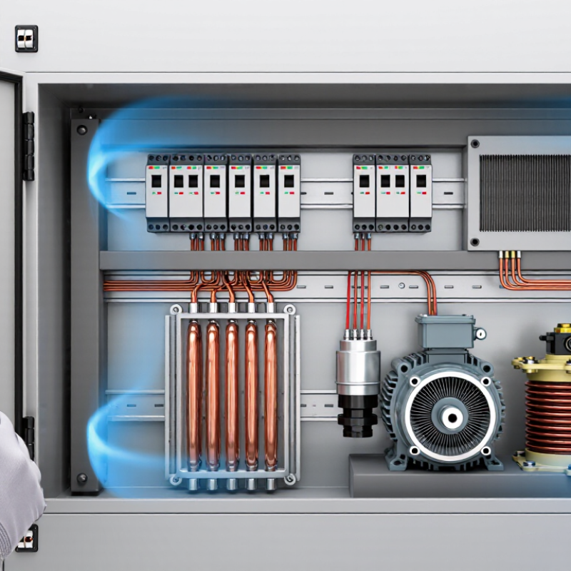
How to Choose Industrial Solid State Relays in 2026
Understanding Industrial Solid State Relay Types and Operating Principles
Industrial solid state relays switch loads electronically, without moving contacts. That means no mechanical contact wear, but heat and leakage current still matter. AC-output relays commonly use thyristors or triacs. Zero-crossing models switch near the AC waveform’s zero point, helping reduce electrical noise with resistive loads. Random-turn-on models can switch at other points in the cycle, which suits phase-control applications. DC-output relays often use MOSFETs or transistors. Check the relay’s output type against the load; an AC relay generally cannot switch a DC load.
A relay’s input signal activates its output through an electrically isolated control circuit. Isolation helps separate control equipment from the switched circuit, but it does not remove the need for correct wiring or protection. Compare load voltage, steady current, and inrush current. Motors and lamps may draw a brief startup surge. Check heat-sink requirements and derating data, too. A current rating on its own can look reassuring, but it may assume ideal cooling. Real enclosures are less tidy.
Tips: Confirm whether the load is AC or DC, then check its startup current and switching frequency. Leave margin for temperature and ventilation. For inductive loads, verify suppression requirements in the relay documentation. Also consider off-state leakage; sensitive loads may respond to a small residual current.
Choosing an industrial solid state relay starts with the load, not the headline current rating. A 10-amp resistive heater behaves differently from a motor that draws a sharp inrush current. Check the load’s steady current, starting current, and duty cycle. Then compare those figures with the relay’s ratings under the actual cabinet temperature. Heat matters. A relay rated for a given current may need a heatsink or reduced load in a warm, crowded enclosure. Leave margin; the exact amount depends on the relay data sheet and operating conditions.
Match the relay’s output type and voltage range to the circuit. AC relays cannot switch DC loads, and vice versa. For AC heaters, zero-cross switching can reduce electrical noise. For fast control or transformer loads, random-turn-on switching may be more suitable, but verify the load requirements. Also check control-input voltage, off-state leakage, and minimum load current. A small indicator lamp may glow faintly from leakage, which surprises people. It is easy to miss in a quick bench test.
Finally, consider switching frequency and failure consequences. Frequent cycling can create more heat, while a shorted relay may leave a load energized. Specify appropriate overcurrent protection and ensure the assembly has ventilation. I would also test the relay with the real load, not only a resistive substitute; that extra check is often skipped, and it can expose an overlooked startup surge.
How to Choose Industrial Solid State Relays in 2026
Selecting Relay Ratings, Isolation, and Thermal Management
A relay’s current rating is only a starting point. Match it to the actual load, including motor-starting inrush, switching frequency, and ambient temperature. The U.S. Department of Energy’s 2014 Improving Motor and Drive System Performance sourcebook reports that motor-driven systems use about 68% of U.S. manufacturing electricity. That scale makes dependable switching more than a catalog checkbox. For a motor or heater, confirm whether the relay supports the load type and its expected surge.
Small details matter. Check off-state leakage, minimum load current, and whether zero-cross or random switching suits the application. Isolation specifications also deserve close attention: verify dielectric withstand and installation clearances against the equipment design. IEC 60947-4-3 provides requirements for semiconductor controllers and contactors, but the selected relay’s own data sheet still governs its operating limits. I still see designs judged by nominal current alone. That shortcut can miss the actual stress.
Thermal calculations turn ratings into practical limits. For example, a 1.6-volt on-state drop at 10 amperes produces about 16 watts of heat. That heat needs a suitable heatsink and airflow, especially inside a crowded control cabinet. Check the manufacturer’s derating curve at the real ambient temperature; a rating measured with a specified heatsink may not apply on a bare panel. Leave margin for dust, restricted ventilation, and switching duty. Those conditions are easy to underestimate.
Estimated SSR conduction loss versus load current, calculated using an example 1.2 V on-state voltage drop.
Conduction loss is estimated as load current × on-state voltage drop. Higher loss means more heat to manage; check the relay datasheet, heatsink requirements, ambient-temperature derating, and required isolation ratings before selecting a device. Actual values vary by relay and operating conditions.
Choosing an industrial solid state relay in 2026 starts with the real load, not the headline current rating. Record load type, voltage, switching frequency, ambient temperature, and available heatsink space. A datasheet number can still mislead. Check thermal derating at the cabinet’s actual temperature, plus off-state leakage and voltage drop. Heat is unforgiving. For inductive loads, review surge protection and coordinate upstream fuses or circuit breakers with the relay’s short-circuit rating.
Confirm that the device and installation meet applicable requirements. IEC 60947-4-3 covers semiconductor controllers and contactors for non-motor loads; motor applications require different checks. Verify isolation, terminal clearances, fault-current coordination, and any required product certification for the destination market. Do not assume a protective feature replaces external overcurrent protection.
Technology choices should fit the control task. Zero-cross switching can reduce electrical noise with many resistive loads, while phase control needs a compatible switching method. Look for clear thermal limits, input compatibility, and status or fault diagnostics when the system needs them. The IEA’s Electricity 2024 report projected global electricity demand growth averaging 3.4% annually through 2026. That forecast is not a relay-sizing rule, but it reinforces the need to check switching duty and heat under real operating conditions. Leave margin, then test the assembly under representative loads. That detail matters.
| Selection dimension | Practical guidance | What to verify before purchase |
|---|---|---|
| Load type and switching mode | Match the relay to an AC or DC load. AC-output relays commonly use triacs or thyristors; DC-output relays commonly use MOSFETs or similar semiconductor devices. Zero-cross switching can reduce electrical noise when switching resistive AC loads. Random-turn-on models allow switching at a commanded point in the AC cycle and may suit phase-control applications. | Confirm load waveform, switching frequency, inrush current, and whether the application needs zero-cross or random-turn-on operation. A standard AC SSR is not automatically suitable for a DC load, or vice versa. |
| Load voltage and current | Choose an output voltage range that covers the supply’s normal operating range and credible transients. Select current capacity using the actual load current and the manufacturer’s derating data; the headline current rating alone does not establish usable current in a particular enclosure. | Check rated output voltage, continuous current at the intended ambient temperature, overload or surge limits, and permitted load type. Allow for motor starting current, transformer inrush, or heater cold resistance where applicable. |
| Input control signal | Match the control input to the controller, such as a PLC output or temperature controller. Common designs accept a specified DC control-voltage range; input current and switching thresholds vary by model. | Verify the input voltage range, input current, polarity, turn-on and turn-off thresholds, and compatibility with the control output. Check isolation specifications between input and output. |
| Heat dissipation and mounting | Semiconductor relays dissipate heat while conducting. At higher currents, a correctly sized heat sink and suitable airflow may be necessary. Mounting orientation, thermal-interface material, and enclosure temperature can affect performance. | Use the relay’s thermal curves and installation instructions to estimate junction or case temperature at the intended load. Check heat-sink requirements, terminal temperature limits, spacing, and ambient-temperature derating. |
| Overcurrent and short-circuit protection | An SSR is not a substitute for branch-circuit or semiconductor overcurrent protection. Fuses or circuit breakers must be selected for the circuit and coordinated with the relay’s withstand characteristics. Semiconductor fuses may be appropriate where fast fault clearing is required. | Check the relay’s short-circuit withstand data and recommended fuse type or maximum fuse rating. Confirm that upstream protection, conductor sizing, and the installation’s fault current are coordinated. |
| Voltage transients and surge protection | Inductive loads and switching events can generate transient overvoltage. Depending on the load and circuit, a suitable snubber, varistor, or other suppression method may help protect the output device and reduce interference. | Review the relay’s transient-voltage rating and the manufacturer’s suppression recommendations. Size any external protection for the circuit voltage, transient energy, and required safety approvals. |
| Leakage current and off-state behavior | Many AC SSRs pass a small off-state leakage current, and some have an off-state voltage across the output. This can cause sensitive loads, indicator lamps, or high-impedance inputs to glow or remain partially energized. | Check maximum off-state leakage current and output voltage. Determine whether the load needs a compatible bleed resistor or other solution, and never assume the output provides mechanical isolation when switched off. |
| Isolation and electrical safety | Input-to-output isolation is important where control and load circuits operate at different potentials. Isolation ratings do not, by themselves, establish that an assembly meets the required installation safety level. | Review dielectric withstand, insulation type, creepage and clearance, pollution degree, and overvoltage category where specified. Confirm suitability for the system voltage and installation environment. |
| Applicable standards and approvals | IEC 62314 addresses solid-state relays. IEC 60947-4-3 covers AC semiconductor controllers and contactors for non-motor loads. Depending on the product and market, industrial control equipment requirements, EMC requirements, and national regulations may also apply. | Check the exact model’s current declaration, test reports, certification marks, and scope. Verify the applicable standard edition and destination-market requirements; a standard’s relevance does not mean every SSR is certified to it. |
| EMC and installation environment | Switching edges, wiring layout, and load type can affect conducted or radiated emissions and susceptibility. Long cable runs, high-noise equipment, vibration, dust, and moisture can also influence system reliability. | Check applicable EMC test information and installation guidance. Assess enclosure rating, operating-temperature range, vibration limits, terminal protection, wiring separation, and any required filtering. |
| Diagnostics and 2026 system needs | For connected equipment, consider whether the control system needs status feedback, temperature monitoring, alarm outputs, or condition data. These features are product-specific; a basic SSR does not necessarily provide diagnostics or communication. | Confirm which measurements and alarms are actually provided, their accuracy and response, and how data reaches the controller. Do not treat monitoring as a replacement for independent protective devices or safe shutdown design. |
| Failure mode and maintenance | Semiconductor outputs can fail short-circuit, leaving a load energized. Applications requiring a guaranteed safe or visible off state may need an appropriately rated series contactor, disconnect, or independent safety function. | Assess the consequences of an SSR failure, define a safe-state response, and plan inspection or replacement based on application risk and operating conditions. Follow applicable machinery and electrical safety requirements. |
Selection note: Ratings, protection features, approvals, and derating limits vary by model. Use the latest technical documentation for the exact relay and have the complete installation assessed against applicable local codes and safety requirements.
Verifying Installation Conditions and Long-Term Reliability
A solid state relay’s catalogue current rating is not a promise of equal performance inside every cabinet. Check the actual load current, switching frequency, ambient temperature, and enclosure ventilation. Then compare them with the relay’s derating curve, not just its headline rating. A compact panel beside a hot motor drive may need a heat sink or lower operating current. Small details matter. Confirm the load type and inrush current, too; a heater and a transformer can stress a relay differently. Review fuse coordination, wiring clearances, and control-signal compatibility before installation.
Reliability depends on what happens after commissioning. Record cabinet temperature and relay case temperature under real operating loads, then inspect for loose terminals, dust, and discoloration during scheduled maintenance. IEC 62314 provides a technical reference for solid-state relay requirements.
For the broader cost of failures, Uptime Institute’s 2024 Annual Outage Analysis reported that 54% of respondents said their most recent significant outage cost over US$100,000. That figure is not specific to industrial relays, but it shows why downtime deserves attention.
Field records are often incomplete, though. Keep a simple log of load changes, alarms, and replacement dates; it can reveal a developing problem before the next shutdown.
Check steady current, startup current, and duty cycle. A heater and motor behave differently. Leave suitable margin for actual conditions.
Heat can reduce the relay’s usable current. Compare the load with its derating curve, and consider a heatsink or lower load. Warm cabinets are easy to underestimate.
No. Match the relay’s output type and voltage range to the circuit.
It can reduce electrical noise with AC heaters. Random-turn-on may suit fast control or transformer loads, but check the load’s requirements.
Verify input voltage, off-state leakage, and minimum load current. Leakage may make a small indicator lamp glow faintly. Easy to miss.
Frequent cycling adds heat. A shorted relay may leave the load energized, so use suitable overcurrent protection and plan for that failure.
Check ventilation, wiring clearances, fuse coordination, and control-signal compatibility. Test with the real load, not only a resistive substitute; startup surges can be overlooked.
Record cabinet and relay case temperatures under operating loads. Inspect terminals, dust, and discoloration; log load changes, alarms, and replacement dates. Records are not always complete, so keep the log simple.
Choosing Industrial Solid State Relays in 2026 starts with understanding how different relay types operate and matching the switching method to the application. Assess the load carefully, including its voltage, current, starting behavior, and switching frequency. These factors help determine the appropriate relay configuration and ratings, while accounting for the conditions under which the equipment will run.
A dependable selection also considers electrical isolation, heat dissipation, and protection features suited to the installation. Check that the relay’s specifications align with relevant equipment standards and the system’s current and anticipated needs. Finally, evaluate the mounting location, ambient temperature, ventilation, wiring, and maintenance access. A careful review of these details can support safe operation, reduce unnecessary wear, and improve long-term reliability.

Copyright © 2026 Altran Magnetics, LLC. All Rights Reserved.