We Design. We Build. We Deliver.
Selecting Three Phase EMI Line Filters in 2026 requires more than comparing catalog prices. Electrification is increasing equipment density, switching speeds, and electromagnetic noise. The International Energy Agency’s Electricity 2024 report expects global electricity demand to grow by about 4% annually through 2026. That growth places greater pressure on industrial drives, photovoltaic inverters, data centers, and charging systems.
The filter must match the application precisely. Check line voltage, continuous current, short-circuit conditions, leakage current, and operating temperature. Then examine insertion-loss curves across the actual noise spectrum. A filter rated for 50/60 Hz may perform poorly against a fast inverter’s megahertz switching noise. Installation matters too. Short bonding paths, correct grounding, and physical separation from noisy cables can determine the final result. Small details matter.
Henry W. Ott, author of Electromagnetic Compatibility Engineering, wrote, “EMC is not a black art; it is an engineering discipline.” That principle remains useful. MarketsandMarkets’ recent EMI shielding research identifies expanding demand across automotive, telecommunications, consumer electronics, and industrial equipment. However, market growth does not make every product suitable. No selection guide is perfect. A filter can look excellent on paper and still fail inside a crowded cabinet. This guide compares Three Phase EMI Line Filters by electrical performance, thermal behavior, safety documentation, installation requirements, and total ownership cost. It also questions common assumptions, including whether maximum attenuation is always the best choice. Sometimes, it is not.
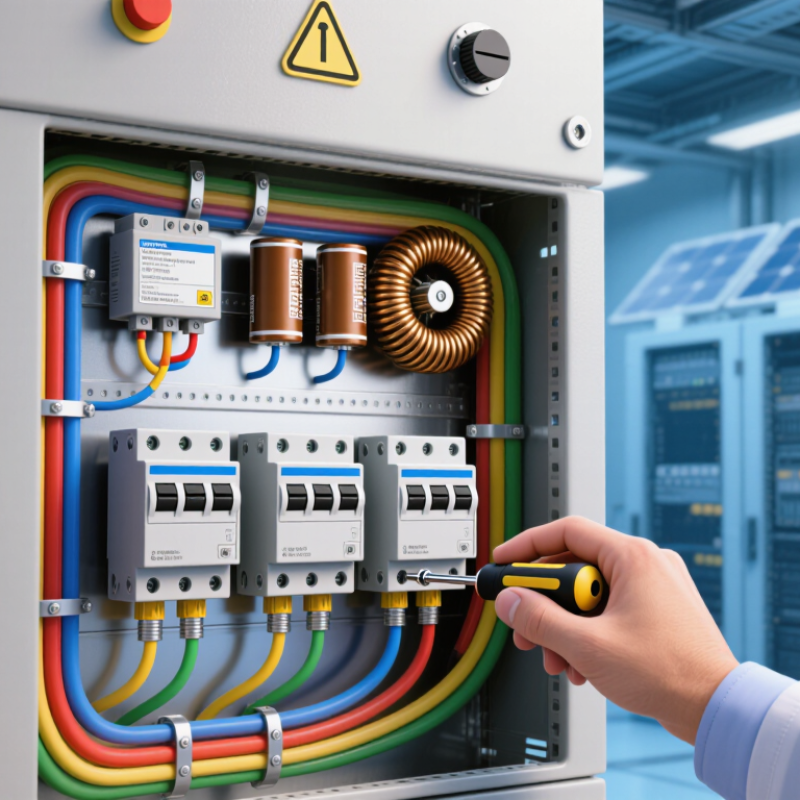
How to Choose Three Phase EMI Line Filters in 2026?
Before choosing a three-phase EMI line filter in 2026, define the electrical environment, not merely the rated voltage. Record line-to-line voltage, frequency, continuous current, overload current, and prospective short-circuit current. Note whether the system uses a neutral conductor. Confirm the phase sequence. It matters.
Motor drives with fast-switching semiconductors can produce strong common-mode noise and high-frequency leakage current. The U.S. Department of Energy’s Industrial Motor System Market Assessment (2022) estimates that motor-driven systems consume about 68% of industrial electricity. Therefore, filter losses and temperature rise deserve serious attention. A filter rated for 32 A at 40°C may require derating inside a hot cabinet. Check the manufacturer’s thermal curves, not only the headline current.
Define the required attenuation by frequency and noise mode. Measure conducted emissions under real load, including acceleration and regenerative braking. Compare results with CISPR 11 and IEC 61800-3 limits for the intended environment. Installation conditions also matter: cable length, shield termination, cabinet bonding, and filter placement can change performance dramatically. Keep input and output cables physically separated.
Do not assume more attenuation is always better. Excessive capacitance can increase leakage current and create residual-current device problems. A catalog selection may pass a laboratory test yet fail after installation. That is the uncomfortable part. Validate the filter with a spectrum analyzer, a representative motor cable, and the actual enclosure.
In 2026, selecting a three-phase EMI line filter begins with the equipment nameplate, not a catalogue photograph. Record line-to-line voltage, tolerance, continuous current, overload current, and system frequency. A 400 V system needs a filter rated above its highest measured voltage. That margin matters during switching and supply fluctuations. Do not confuse thermal current with brief peak current. An 18 A drive may still need a filter tested for acceleration surges. Measure it.
Match the filter to the phase arrangement. Three-phase, three-wire systems differ from three-phase, four-wire systems with a neutral. For delta and wye installations, check how common-mode and differential-mode noise returns through the filter. The current rating should exceed real operating current. Avoid extreme oversizing, which can reduce attenuation at the working load. Check insertion loss across the actual noise band, especially around switching frequencies and harmonics. A filter optimized at 150 kHz may perform poorly near 8 kHz. Frequency is not decorative.
Confirm leakage current, grounding method, enclosure temperature, and terminal clearances before installation. Poor bonding can erase a well-designed filter’s benefit. Keep motor cables separate from input wiring. Mount the filter close to the power entry point. During commissioning, compare conducted-noise readings with and without the filter. A spectrum analyzer or compliant receiver can reveal unexpected peaks. One mistake is trusting nominal current while ignoring temperature derating. Recheck the calculation at the hottest cabinet temperature. The datasheet rarely tells the whole story.
Match the filter rating to the system voltage, load current, operating frequency, and phase configuration. The chart shows representative engineering examples using a 25% current margin between the continuous load and the selected filter rating.
Selection guide: Common three-phase systems include 230 V, 400 V, 480 V, and 690 V nominal line-to-line supplies. Select a filter with a voltage rating equal to or higher than the actual system voltage and a continuous current rating above the maximum RMS load current, including expected overload and inrush conditions.
For frequency, confirm compatibility with the 50 or 60 Hz power system and review conducted EMI performance across the applicable 150 kHz–30 MHz measurement range. For phase configuration, verify whether the installation is three-phase three-wire or three-phase four-wire with neutral, and confirm the required PE and leakage-current characteristics.
How to Choose Three Phase EMI Line Filters in 2026?
Evaluate Attenuation Performance Across Relevant Interference Frequencies
Choosing a three phase EMI line filter starts with the interference spectrum, not the product label. Measure conducted noise under real operating conditions. Include the inverter’s switching frequency and its harmonics. Industrial equipment often requires attention from 150 kHz through 30 MHz. Higher frequency behavior can also affect sensitive control circuits.
Review insertion loss for both common-mode and differential-mode noise. A filter may perform well at one frequency and poorly at another. Ask for curves tested with realistic source and load impedances. Laboratory results can change when cable length, grounding, or enclosure layout changes. Small details matter here. Compare attenuation near the actual noise peaks, not only the maximum value.
Check performance at the intended current, voltage, and temperature. Magnetic components can saturate during heavy loading. Capacitor characteristics may shift as temperature rises. I have seen impressive test graphs lose practical value after installation. That does not make the data useless. It means the test setup needs closer examination. Verify leakage current and protective grounding requirements before approval. A filter should reduce interference without creating new operational concerns. Retest after mounting, because the cabinet can become part of the circuit.
When selecting a three-phase EMI line filter in 2026, begin with safety documentation, not marketing claims. Check applicable IEC requirements, insulation ratings, creepage distances, and certified voltage limits. A filter rated for 480 V may not suit every transient environment. Review the test conditions carefully. Certification details matter.
Leakage current deserves special attention in systems using several filters. Y capacitors can send measurable current toward protective earth, especially in long cable installations. Measure leakage at the assembled machine, not only from the filter datasheet. I once underestimated cable capacitance during a panel review. That assumption needed correction. Use residual-current protection compatible with the equipment and local electrical rules.
Grounding must provide a short, low-impedance path for high-frequency noise. Keep the filter’s protective-earth connection wide, short, and bonded directly to the metal enclosure. Avoid routing it beside sensitive control wiring.
Thermal limits are equally practical. Compare the filter’s rated current with real motor loads, ambient temperature, switching duty, and enclosure ventilation. Apply derating when the cabinet feels warm. A small temperature rise can become significant after hours of operation.
Check terminal temperature, not just surface temperature. The datasheet is important, but the installed environment decides whether the design remains reliable.
How to Choose Three Phase EMI Line Filters in 2026?
Choosing a three-phase EMI line filter starts with cabinet reality, not catalog ratings. Measure the available width, depth, and clearance around terminals. Leave room for bending cables and checking connections. A filter may fit on paper but fail inside a crowded enclosure. Space matters.
Verify the system voltage, frequency, rated current, neutral arrangement, and protective-earth connection. Check leakage current before installation, especially near sensitive equipment. Compatibility also depends on the noise source. Motor drives, switching supplies, and heating controllers produce different interference patterns. Request insertion-loss data for both differential-mode and common-mode noise. Do not trust a single curve blindly. Installation wiring can change performance significantly. Measurements expose assumptions.
Test the filter under realistic load conditions. A pre-compliance scan can reveal problems before formal testing, but it is not a certification. Use calibrated instruments and record cable routing, load current, and enclosure conditions. For long-term reliability, examine terminal quality, insulation ratings, vibration resistance, humidity protection, and temperature rise. Apply current derating when the cabinet runs hot. Thermal cycling and insulation-resistance checks add useful evidence. No checklist catches every failure. I have seen a technically suitable filter underperform because its ground path was too long. Review the installation after testing, not only the component datasheet.
| No. | Selection Dimension | Recommended Verification | Practical Reference Data | Key Risk if Incorrect | Acceptance Check |
|---|---|---|---|---|---|
| 1 | System voltage and wiring | Confirm line-to-line voltage, frequency, neutral connection, protective-earth arrangement, and whether the filter is installed on a balanced or unbalanced load. | Common industrial systems include 380–415 V AC at 50 Hz and 440–480 V AC at 60 Hz. Select a rated voltage above the highest continuous operating voltage and account for permitted overvoltage. | Insulation stress, excessive leakage current, nuisance tripping, or inadequate common-mode attenuation. | Compare the nameplate rating with the measured supply and verify the wiring diagram before energizing the system. |
| 2 | Continuous current | Use the highest true RMS input current, including overload, acceleration, regeneration, harmonic current, and ambient-temperature derating. | A practical initial margin is 20–30% above the maximum measured or calculated continuous current. For a 32 A load, a filter rated for at least 38.4–41.6 A is a reasonable starting point, subject to the manufacturer’s derating curve. | Overheating, reduced service life, thermal shutdown, or excessive voltage drop. | Check RMS current at full load and confirm that the filter terminal, conductor, and protective-device ratings are coordinated. |
| 3 | Installation envelope | Measure the available width, height, depth, terminal clearance, cable-bending radius, ventilation path, and access space for inspection. | Allow additional space for cable routing and heat dissipation. A compact panel installation commonly requires at least 25–50 mm of free air around heat-producing components, unless the equipment instructions specify otherwise. | Forced bending, loose terminals, blocked cooling airflow, or impossible maintenance access. | Create a scale drawing showing the filter body, terminals, cable radius, enclosure barriers, and adjacent components. |
| 4 | Filter topology | Determine whether the interference is mainly common-mode, differential-mode, or a combination of both. | Common-mode chokes primarily address noise shared by the phase conductors relative to earth. Differential-mode capacitors address noise between phases. Many three-phase filters combine both functions. | A filter may show good laboratory insertion loss but provide limited improvement in the actual installation. | Use conducted-noise measurements or a spectrum analyzer with suitable probes to identify the dominant noise path. |
| 5 | Insertion-loss target | Review insertion-loss curves across the actual interference band rather than selecting a filter by its maximum headline value. | For many industrial switching systems, evaluate at least 150 kHz–30 MHz, the frequency range commonly used for conducted-emission assessment. The required attenuation depends on the noise margin and system layout. | Insufficient attenuation at the problem frequency or unexpected resonance with the converter and cable network. | Compare the measured before-and-after spectrum using the same operating point, cable length, grounding, and detector settings. |
| 6 | Leakage current and earth connection | Calculate the combined leakage current from the filter, drive, motor cable, and other connected equipment. | Y-capacitor current increases with capacitance, line voltage, and frequency. For a balanced three-phase capacitor network, the approximate RMS current can be estimated using I = 2πfCV for each capacitor branch, subject to the actual circuit configuration. | Residual-current-device tripping, touch-current concerns, or ineffective high-frequency bonding. | Measure protective-earth current under normal and single-fault test conditions where required by the applicable safety standard. |
| 7 | Temperature and derating | Check the operating-temperature range, enclosure temperature, altitude, airflow, and current-derating curve. | A filter rated at 40 °C may require current reduction at higher ambient temperatures. The actual allowable current must be taken from the applicable thermal curve, not inferred from the nominal rating. | Capacitor aging, insulation degradation, increased losses, and premature failure. | Measure the hottest accessible surface during worst-case operation and compare it with the specified operating limits. |
| 8 | Voltage drop and power loss | Review impedance, resistance, and rated voltage-drop data at the expected current and frequency. | The allowable voltage drop is application-specific. Low-voltage-control systems and high-power drives can be particularly sensitive to additional impedance during acceleration or load transients. | Reduced motor torque, undervoltage faults, additional heat, or unstable equipment operation. | Measure line-to-line voltage before and after the filter at idle, rated load, and transient conditions. |
| 9 | Short-circuit coordination | Confirm short-circuit withstand, prospective fault current, upstream protection, and any required external fusing. | The filter’s short-circuit rating must be equal to or greater than the available fault level when properly protected. Fuse type, rating, and maximum interrupting capacity must follow the approved installation instructions. | Unsafe fault clearing, enclosure damage, or invalid certification assumptions. | Document the fault-current calculation and verify coordination with the protective device. |
| 10 | Mechanical and environmental rating | Match enclosure protection, vibration, shock, humidity, corrosion, and contamination requirements to the installation location. | Indoor control cabinets, outdoor cabinets, washdown areas, and high-vibration machinery require different mechanical and environmental provisions. The filter itself may need additional enclosure protection. | Corroded terminals, insulation tracking, mechanical loosening, or reduced dielectric strength. | Verify the declared environmental rating and use suitable cable glands, bonding surfaces, and fasteners. |
| 11 | Grounding and cable layout | Separate the unfiltered and filtered cable paths, minimize conductor loop area, and bond the filter case directly to the metal mounting panel. | Short, wide, low-inductance bonds are generally more effective at high frequency than long pigtail wires. Keep input and output conductors physically separated. | Signal bypass around the filter, common-mode radiation, and poor repeatability between installations. | Inspect the panel bond, cable separation, shield termination, and PE continuity before performance testing. |
| 12 | Safety and compliance documents | Request datasheets, wiring diagrams, safety approvals, leakage-current information, installation instructions, and test conditions. | Relevant documents may reference IEC 60939 requirements for passive filter units, UL 1283 requirements for electromagnetic-interference filters, and applicable EMC standards such as CISPR 11 or EN 55011. | Unverified ratings, incorrect assumptions about certification scope, or failed system-level compliance testing. | Confirm that the approval applies to the intended voltage, current, installation method, and final equipment category. |
| 13 | Installation and commissioning tests | Perform visual inspection, PE continuity, insulation resistance where permitted, torque verification, leakage-current measurement, and conducted-emission testing. | Test with the actual converter, motor or load, cable length, switching frequency, enclosure, and operating modes. Laboratory insertion-loss data alone does not represent complete system performance. | Intermittent faults, unexpected emissions, damaged insulation, or non-repeatable results. | Record test date, instrument, setup, load condition, spectrum, torque values, and measured leakage current. |
| 14 | Long-term reliability | Evaluate capacitor construction, thermal margin, expected operating hours, vibration exposure, service access, and replacement availability. | Film capacitors are commonly selected for high pulse and self-healing performance, while all capacitors are still affected by temperature, voltage stress, ripple current, and environmental conditions. | Progressive capacitance loss, increased leakage, overheating, or unplanned downtime. | Use a preventive-maintenance schedule based on operating temperature, duty cycle, inspection findings, and system criticality. |
| 15 | Final selection record | Create a controlled specification containing electrical, mechanical, environmental, safety, EMC, and maintenance requirements. | The final record should include voltage, frequency, current, dimensions, terminal arrangement, leakage current, attenuation requirement, temperature range, short-circuit coordination, and test results. | Uncontrolled substitutions or future installation changes that invalidate the original evaluation. | Approve the filter only after document review, physical fit verification, safety checks, and system-level EMC testing. |
Record line voltage, voltage tolerance, continuous current, overload current, frequency, and phase arrangement. Measure it.
Choose a filter rated above the system’s highest measured voltage. Switching events and supply fluctuations need headroom.
No. It should exceed real operating current and tolerate acceleration surges. An 18 A drive may need more.
Yes. A neutral changes the noise-return path. Check delta or wye wiring, neutral connections, and protective-earth bonding.
Insertion loss depends on frequency. A filter effective near 150 kHz may perform poorly around 8 kHz and its harmonics.
Mount it near the power-entry point. Keep motor cables separate from input wiring and allow room for cable bends.
Long ground paths, poor bonding, tight terminals, and incorrect cable routing can weaken attenuation. A good component can still underperform.
Compare conducted-noise readings with and without the filter. Record load current, cable routing, cabinet temperature, and enclosure conditions.
Review terminal quality, insulation ratings, vibration resistance, humidity protection, temperature rise, and current derating. No checklist catches everything.
Hot enclosures can reduce allowable current. Recheck derating at the highest expected temperature, not room temperature.
Choosing Three Phase EMI Line Filters in 2026 begins with clearly defining the equipment’s operating environment and electromagnetic interference requirements. Consider the system voltage, current capacity, frequency range, phase configuration, and expected load conditions before comparing filter specifications. Attenuation should be evaluated across the interference frequencies most relevant to the application, rather than relying on a single performance figure. This helps ensure the filter can reduce both common-mode and differential-mode noise effectively.
Safety and long-term reliability are equally important. Confirm compliance with applicable safety standards, acceptable leakage current, proper grounding, insulation requirements, and thermal limits under continuous operation. The filter should also fit the available installation space, connect smoothly with existing equipment, and remain compatible with the system’s electrical and mechanical design. Before deployment, verify performance through appropriate testing, including temperature, load, and noise assessments. A careful selection process improves equipment stability, reduces interference-related problems, and supports dependable operation throughout the filter’s service life.

Copyright © 2026 Altran Magnetics, LLC. All Rights Reserved.