We Design. We Build. We Deliver.
Choosing the best Single Phase EMI Filters from China requires more than comparing prices or polished product photos. Buyers must match each filter with the equipment’s voltage, current, frequency, and installation environment. A filter for a compact medical device may need different leakage-current control than one used in an industrial motor cabinet. Small details matter, including terminal design, enclosure space, grounding method, and operating temperature.
Reliable evaluation begins with technical evidence. Request datasheets showing insertion loss across relevant frequency bands, rated current, insulation resistance, dielectric strength, and leakage current. Review test conditions carefully. A claimed attenuation figure may not represent your actual circuit. Ask suppliers for samples, factory inspection records, quality-control procedures, and applicable certifications for your target market. Experienced buyers also test filters under real loads, using cable lengths and grounding arrangements similar to production equipment. That practical step often reveals noise paths missed in laboratory summaries.
No filter is perfect. The “best” choice depends on risk, performance, supply stability, and total cost. A low-priced component can become expensive when it causes repeated compliance failures or production delays. Look for manufacturers with documented experience, consistent batch records, responsive engineers, and clear traceability. It is also wise to confirm customization limits before approving drawings. Some suppliers communicate well during sampling but respond slowly after an order. That weakness deserves attention. This guide compares key specifications, supplier practices, testing expectations, and application factors, helping international buyers make a more reliable decision when sourcing Single Phase EMI Filters from China.
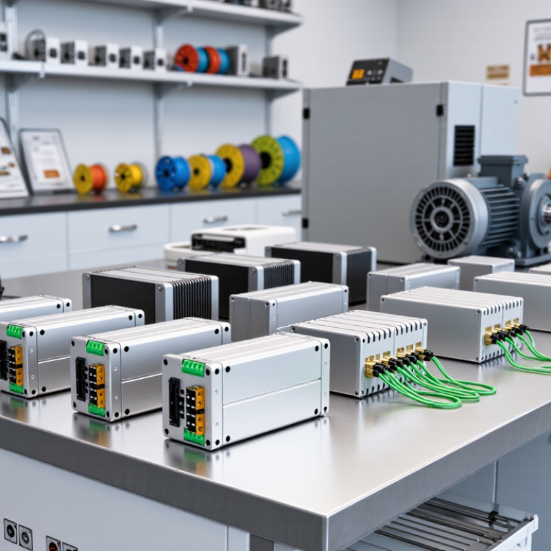
What Are China’s Best Single-Phase EMI Filters for Buyers?
A single-phase EMI filter is a passive device that reduces unwanted electromagnetic noise on an AC power line. It usually combines inductors, capacitors, and discharge resistors inside a compact housing. The filter blocks high-frequency interference while allowing normal 50 or 60 Hz power to pass. Simple in theory.
Its purpose is practical. It can reduce conducted emissions from switching supplies, motors, inverters, and control equipment. Common-mode noise travels along conductors in the same direction, while differential-mode noise moves between line and neutral. Different filter components address these paths. During equipment testing, engineers check insertion loss, leakage current, temperature rise, and grounding performance. A filter that works well in a laboratory may perform differently inside a crowded cabinet.
For buyers comparing single-phase EMI filters from China, technical documents deserve close attention. Check the rated voltage, operating current, frequency range, attenuation curves, terminal design, and enclosure material. Ask whether test conditions match your application. Installation also matters. Short connections, proper grounding, and separation from noisy cables often improve results. A higher current rating is not automatically better. Oversized filters may increase cost and leakage current without solving the real problem. One common mistake is choosing by appearance alone. It is better to review samples, inspect workmanship, and test the filter with the actual load. The first selection may be wrong. That is normal, but ignoring the evidence is not.
The best single phase EMI filter depends on the equipment, not its country of origin. Buyers should match the rated voltage, operating current, and frequency with real working conditions. Leave reasonable headroom, but avoid oversized parts that increase cost and leakage current. A factory control panel, medical device, and household appliance may need very different filtering performance.
Insertion loss deserves close attention. Compare attenuation across the actual interference range, not only one impressive frequency point. Check common-mode and differential-mode results separately. A filter with strong high-frequency performance may offer limited protection at lower frequencies. Review the test circuit, impedance, and measurement conditions in the datasheet. Without this context, numbers can mislead.
Safety specifications need equal weight. Examine leakage current, dielectric withstand voltage, insulation resistance, temperature range, and flammability information. Confirm terminal size and mounting space before ordering samples. I also inspect the enclosure, grounding path, and cable layout during practical testing. A good filter can perform poorly after careless installation. That mistake is easy to make. Buyers should request traceable test reports and production consistency data. I would not rely on a polished datasheet alone. Ambient temperature, load changes, and long operating hours can expose weaknesses that short bench tests miss.
Differential-mode filters target noise between line and neutral. Common-mode filters address noise appearing on both conductors.
Application details matter. Medical equipment requires careful leakage-current evaluation and documented safety testing. Industrial cabinets may need a higher current rating and stronger terminals. Outdoor systems need better moisture and temperature resistance. Buyers should request insertion-loss curves, insulation data, safety certifications, and test reports. Do not rely on a product photo.
Real performance can differ from laboratory results. Cable length, grounding, enclosure design, and mounting position change filter behavior. A filter may pass a datasheet test yet perform poorly after installation. This is often overlooked.
Ask for sample testing under the intended load. Review thermal rise after continuous operation. The best choice is not always the filter with the highest attenuation; it must fit the complete electrical system.
What Are China Best Single Phase EMI Filters for Buyers?
The best single-phase EMI filter is not simply the one with the highest insertion-loss number. Buyers should match the filter with the equipment’s voltage, current, frequency, and connection method. Check whether it handles line-to-neutral noise, common-mode interference, or both. A filter rated for 250 V and 10 A may fail in a warmer cabinet or under repeated overloads. Measure insertion loss across the working frequency range, not at one impressive point.
Safety requires closer inspection. Review leakage current, insulation resistance, dielectric strength, grounding, and temperature rise. Ask for current test reports and certificates linked to the exact model. Terminal spacing should suit the installation environment. The enclosure must also resist dust, vibration, and accidental contact. Compatibility is practical. Confirm dimensions, mounting holes, cable direction, and available space around the filter. A perfect electrical match may still be impossible to install.
Tips: Test a sample in the final cabinet. Keep cable paths short. Separate filtered and unfiltered wires. Compare results before and after installation. Datasheet figures can look better than field performance. I have seen wiring layout reduce the expected benefit noticeably. That is not a failure of the filter alone. It is a reminder to evaluate the complete system with repeatable measurements and qualified technical review.
| Filter Configuration | Typical Electrical Rating | Typical Insertion Loss | Typical Leakage Current | Safety and Protection Features | Installation and Compatibility | Best Evaluation Criteria for Buyers |
|---|---|---|---|---|---|---|
| Compact Chassis-Mount Filter | 250 VAC, 50/60 Hz 3–10 A |
Approximately 20–50 dB from 0.15–30 MHz, depending on load impedance and circuit design | Typically below 0.5–2.0 mA at 250 VAC | Metal case, line-to-ground capacitors, line-to-line capacitor, discharge resistor, and optional overcurrent protection | Suitable for control cabinets, power supplies, instruments, and compact industrial equipment | Check terminal spacing, case grounding, rated current at ambient temperature, and attenuation under the intended source and load impedance |
| High-Current Chassis-Mount Filter | 250 VAC, 50/60 Hz 10–30 A |
Approximately 15–45 dB from 0.15–30 MHz; performance is strongly affected by conductor routing | Typically below 1.0–3.5 mA at 250 VAC | Low-resistance terminals, reinforced insulation, grounded metal housing, and thermal derating requirements | Suitable for motors, heating equipment, industrial power supplies, and high-load single-phase systems | Verify continuous current, inrush-current tolerance, temperature rise, conductor size, and whether the filter requires a dedicated protective earth connection |
| DIN-Rail Single-Phase Filter | 250 VAC, 50/60 Hz 6–20 A |
Approximately 20–50 dB from 0.15–30 MHz when installed with short, separated input and output wiring | Typically below 0.5–2.5 mA at 250 VAC | Touch-protected terminals, DIN-rail mounting, grounding provision, and flame-retardant insulating materials | Designed for electrical control panels, PLC systems, automation cabinets, and modular equipment | Assess rail compatibility, terminal accessibility, enclosure space, input-output separation, and the filter’s permissible operating temperature |
| IEC Inlet with Integrated EMI Filter | 250 VAC, 50/60 Hz 1–10 A |
Approximately 15–40 dB from 0.15–30 MHz | Typically below 0.5–1.5 mA at 250 VAC | Integrated appliance inlet, fuse option, switch option, finger-safe design, and protective-earth connection | Suitable for laboratory equipment, office equipment, test instruments, and low-to-medium power devices | Confirm IEC inlet dimensions, fuse type, switch rating, plug compatibility, panel cutout, and available rear clearance |
| Low-Leakage Filter | 250 VAC, 50/60 Hz 1–20 A |
Approximately 10–40 dB from 0.15–30 MHz; attenuation may be lower than standard filters at some frequencies | Typically below 0.1–0.5 mA at 250 VAC | Reduced line-to-ground capacitance, reinforced insulation, protective-earth connection, and controlled discharge characteristics | Suitable for measurement instruments, patient-connected equipment, audio systems, and installations sensitive to earth leakage | Prioritize leakage-current test data, protective-earth continuity, dielectric withstand voltage, and the required equipment safety classification |
| Medical-Application Single-Phase Filter | 250 VAC, 50/60 Hz 3–20 A |
Approximately 15–45 dB from 0.15–30 MHz, subject to the final equipment enclosure and cable layout | Often designed for very low leakage, commonly below 0.1–0.5 mA; the exact limit depends on the equipment application | Reinforced insulation, high dielectric withstand, low leakage design, protective-earth provisions, and documented safety testing | Suitable only when the complete end product is designed and tested for the applicable medical electrical safety requirements | Do not rely on the filter alone; review the complete system’s leakage current, creepage, clearance, dielectric test, earth continuity, and risk-management documentation |
| Two-Stage EMI Filter | 250 VAC, 50/60 Hz 3–20 A |
Approximately 35–70 dB from 0.15–30 MHz under specified laboratory test conditions | Typically below 0.5–3.0 mA at 250 VAC, depending on capacitor configuration | Multiple common-mode chokes, differential-mode inductance, safety-rated capacitors, shielding, and a grounded enclosure | Suitable for high-noise switching power supplies, variable-speed equipment, data-processing equipment, and demanding EMC applications | Request insertion-loss curves, common-mode and differential-mode data, saturation-current information, and test conditions used to obtain the published results |
| Three-Line or Neutral-Configuration Filter | 250 VAC, 50/60 Hz 6–30 A |
Approximately 20–55 dB from 0.15–30 MHz, depending on the neutral and protective-earth arrangement | Typically below 1.0–3.5 mA at 250 VAC | Balanced conductor design, safety-rated capacitors, reinforced insulation, and clearly identified line, neutral, and earth terminals | Suitable for single-phase line-and-neutral systems where balanced filtering and defined conductor routing are required | Confirm the actual supply topology, neutral switching requirements, earth arrangement, terminal markings, and compatibility with residual-current protection |
| Feed-Through or Bulkhead Filter | 250 VAC, 50/60 Hz 5–30 A |
Approximately 30–70 dB from 0.15–30 MHz when correctly mounted through a conductive enclosure wall | Typically below 0.5–3.0 mA at 250 VAC | Bulkhead shielding, conductive mounting surface, high-voltage insulation, and short internal connection paths | Suitable for shielded cabinets, industrial enclosures, instrumentation, and applications requiring high enclosure-level noise control | Evaluate panel thickness, mounting-hole dimensions, gasket or bonding requirements, enclosure conductivity, and separation of filtered and unfiltered zones |
| Compact PCB-Mount Filter | 250 VAC, 50/60 Hz 1–6 A |
Approximately 10–35 dB from 0.15–30 MHz, depending on PCB layout and the surrounding circuit | Typically below 0.5–1.5 mA at 250 VAC | Safety-rated capacitors, creepage and clearance provisions, flame-retardant housing, and defined pin spacing | Suitable for compact power supplies, appliances, chargers, and embedded control boards | Check PCB creepage and clearance, pin temperature rating, solder-process compatibility, conducted-emission test results, and fuse coordination |
| Buyer’s technical note: The values above are representative engineering ranges rather than guaranteed product specifications. Actual EMI attenuation depends on frequency, source impedance, load impedance, grounding, cable length, enclosure design, installation method, and filter orientation. Before purchase, request the complete datasheet, insertion-loss curves, leakage-current results, dielectric withstand test voltage, operating-temperature derating, applicable safety approvals, and a sample for conducted-emissions verification. | ||||||
What Are China’s Best Single-Phase EMI Filters for Buyers?
Choosing a single-phase EMI filter requires more than comparing prices. Match its rated voltage and current to the actual equipment load. Leave practical headroom, especially for motors and switching power supplies. Check insertion loss across the interference range, not only at one frequency. Leakage current also matters in sensitive installations. I usually inspect the filter’s terminals, enclosure rating, and heat tolerance before ordering. A compact filter may look efficient, but limited airflow can shorten its service life.
Installation quality often decides whether the filter performs well. Mount it close to the equipment entry point. Keep input and output wires physically separated. Their paths should not run parallel for long distances. Use a short, low-impedance protective earth connection. Tighten terminals to the specified torque. Loose wiring creates heat and unexpected noise. I have seen well-selected filters underperform because installers routed clean and noisy cables together. That detail is easy to miss.
Maintenance should include visual checks, terminal inspections, and temperature observations during normal operation. De-energize the system before opening any enclosure. Qualified personnel should verify insulation and grounding safely. Record when interference appears, such as during startup or heavy load changes. This record can reveal whether the filter is aging or the equipment has changed. Replacement is sensible when the housing cracks, terminals discolor, or performance declines. My own selection process is not perfect; real loads can differ from catalog assumptions. Rechecking measurements after installation remains worthwhile.
It reduces conducted electrical noise between equipment and the power line. It protects cleaner operation. Results depend on installation.
A compact inlet filter combines a connector, fuse holder, and filtering circuit. It fits office equipment, laboratory instruments, and small control panels. Replacement access may be limited.
Two-stage filters provide stronger attenuation across broader frequency ranges. They suit switching supplies, motor drives, and sensitive measurement equipment. Higher performance is not always necessary.
Differential-mode filters target noise between line and neutral. Common-mode filters address noise appearing on both conductors. Some systems require both methods.
Check voltage, current, frequency, leakage current, and connection method. A 250-volt, 10-amp rating may not suit a hot cabinet. Repeated overloads can change performance.
Request insulation resistance, dielectric strength, grounding, and temperature-rise data. Ask for reports linked to the exact model. Do not trust photographs alone.
Cable length, grounding, enclosure design, and mounting position can change results. Keep filtered and unfiltered wires separate. Short cable paths usually help.
Yes. Test the sample inside the final cabinet under the intended load. Measure noise before and after installation. Review continuous-operation temperature rise. Laboratory results may look better.
Single Phase EMI Filters are essential components for reducing unwanted electromagnetic interference in electrical equipment and power systems. This article explains their definition, purpose, and operating principles, showing how they suppress conducted noise while allowing normal power transmission. It also outlines the key specifications buyers should compare, including rated voltage and current, insertion loss, frequency range, leakage current, impedance, safety certifications, and environmental durability.
The guide reviews common filter types and their suitable applications, from compact equipment protection to industrial control systems. It also explains how to evaluate performance, safety, compatibility, and reliability before purchase. Buyers will learn to consider load characteristics, installation space, grounding requirements, thermal conditions, and maintenance needs. Proper selection and installation can improve equipment stability, reduce interference-related failures, and extend service life, while periodic inspection helps ensure continued filtering performance.

Copyright © 2026 Altran Magnetics, LLC. All Rights Reserved.