We Design. We Build. We Deliver.
Choosing the right Energy Storage System DC Contactors is a practical safety decision, not a simple purchasing task. These components control high-voltage battery currents during charging, discharging, isolation, and emergency shutdown. A contactor may look compact on a test bench, yet its contacts can face intense arcing inside a 1,000-volt battery enclosure. The wrong model can create overheating, welded contacts, unwanted downtime, or dangerous isolation failures.
This guide presents seven practical tips for evaluating contactors in energy storage applications. It considers rated voltage, continuous current, breaking capacity, precharge requirements, coil control, insulation, sealing, and expected service life. Engineers should compare manufacturer datasheets with real operating conditions, including ambient temperature, switching frequency, cable resistance, and available fault current. Certification evidence and traceable test records also matter. Marketing language alone is not enough.
Field experience often reveals details that laboratory figures hide. A contactor rated for a certain current may perform differently inside a hot cabinet with limited airflow. It may also require suppression circuitry or a specific mounting position. Small mistakes matter. No checklist is perfect. Some projects still expose overlooked assumptions after installation. Therefore, qualified professionals should validate the selected Energy Storage System DC Contactors through design reviews, prototype testing, and documented maintenance planning. The following tips aim to make that process clearer, more disciplined, and easier to verify before equipment reaches the field.
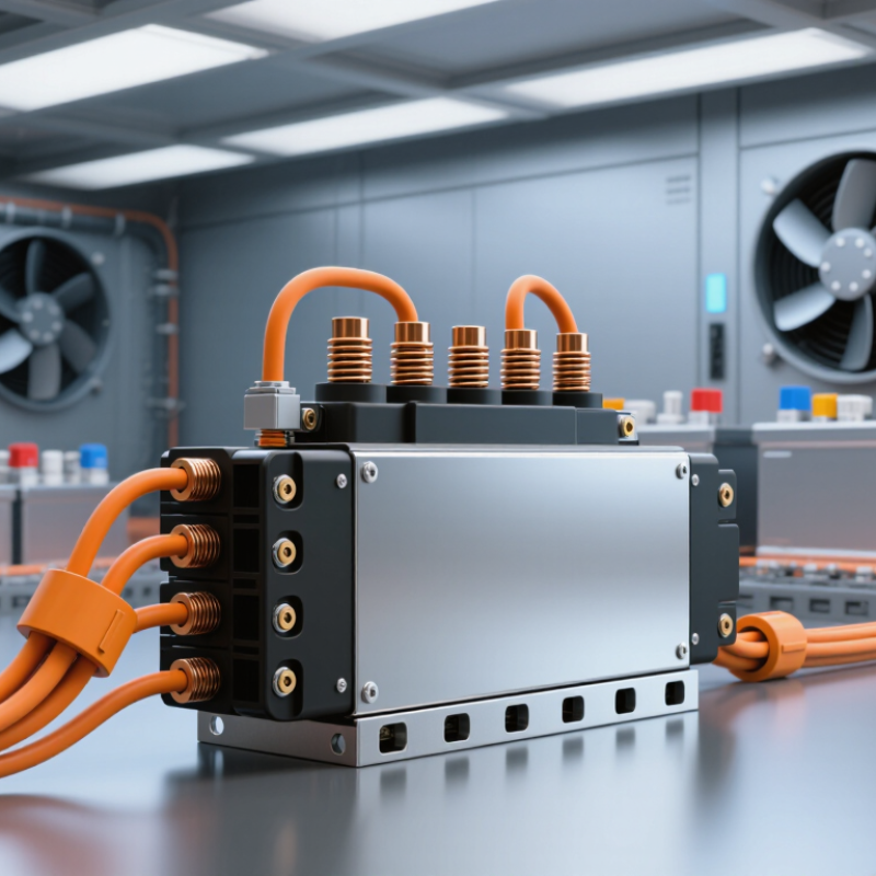
Choosing an energy storage system (ESS) DC contactor starts with the real electrical envelope, not the nominal battery label. Many designs operate between 600 and 1,500 VDC. That range changes insulation spacing, switching stress, and test requirements. Record the highest charged voltage, minimum voltage, and expected current at each operating state. Nominal data misleads.
The fault envelope deserves equal attention. A 10–100 kA prospective short-circuit range can determine whether a contactor survives, welds, or fails open. Use battery impedance, busbar length, fuse response, and inverter capacitance to estimate the first milliseconds. Do not treat a fuse as instant protection. Real tests often expose cable inductance and arc behavior that spreadsheets miss. Measure it when possible. Select continuous, making, and breaking ratings separately. Also verify polarity, precharge duty, thermal rise, and isolation after fault interruption.
In field reviews, the weakest assumption is often the fault current value. A conservative estimate may increase cost, but an optimistic one can distort every protection decision. Ask for evidence: DC load tests, dielectric reports, endurance data, and defined failure modes. Check performance at 1,500 VDC, not only at a comfortable laboratory voltage. Temperature matters. At low temperatures, batteries can deliver different current profiles; at high temperatures, contact resistance can rise. Document the limits clearly, and revisit them after pack, fuse, or inverter changes.
Match the contactor’s DC voltage and current ratings with the battery’s highest operating limits. Do not size from nominal voltage alone. A 800 V battery may exceed 900 V during charging. Check continuous current, overload current, and the expected fault level. IEC 60947-4-1 provides a useful framework for contactor performance and verification.
DC-1 applies to non-inductive or slightly inductive loads, where interruption is comparatively gentle. Energy storage systems are rarely perfectly gentle. Cable inductance, capacitors, and inverter input stages can create sharper arcs.
Confirm the manufacturer’s stated utilization category, voltage, current, and electrical endurance under your actual load conditions. Look for DC making and breaking ratings, not only an AC rating. It is a common mistake.
Review the time constant and switching frequency. A contactor that passes one clean test may wear quickly after thousands of daily cycles. Check pre-charge requirements, auxiliary contact feedback, insulation voltage, and creepage distances. Thermal derating matters inside a sealed cabinet, especially near busbars. Field engineers should compare test data with measured battery behavior, including cold-start voltage and emergency disconnection. Leave margin for aging, but avoid excessive oversizing without verification. Bigger is not automatically safer. Record the assumptions, because an overlooked inductive load can invalidate an otherwise careful selection.
Choosing an energy storage system DC contactor starts with the real continuous load, not the nominal battery label. Size the contactor for at least 125% of the maximum operating current. For a 400-ampere load, select a continuous rating of 500 amperes or higher. This margin handles cable heating, inverter demand, and small measurement errors. It also protects performance at a 40°C ambient temperature.
Temperature changes everything. A contactor rated at room temperature may carry less current inside a warm cabinet. Check the derating curve at 40°C, including nearby busbars, chargers, and cooling limitations. Confirm the maximum DC voltage and the contactor’s ability to interrupt the expected fault current.
Continuous current and interrupt rating are different specifications. Do not confuse them. Review coil voltage, power consumption, auxiliary contacts, electrical endurance, and mechanical life. Precharge compatibility matters when capacitive inverter inputs create high inrush current.
Installation details often expose weak designs. Keep high-current paths short, use correctly tightened terminals, and leave space around heat-producing components. Measure temperature at the terminals after sustained operation. A thermal camera can reveal a loose connection before damage appears. A clean calculation is not enough. Field conditions may differ from the test setup. Datasheets can also leave installation assumptions unclear, so request clarification and document the selected rating. Check the system again after seasonal temperature changes and extended charging cycles.
7 Tips for Choosing Energy Storage System DC Contactors
Choose Coil Control for 12/24 VDC Systems and <1 W Hold Power
Coil control deserves careful attention in battery energy storage systems. Many control circuits operate at 12 or 24 VDC, so the contactor coil should match the available voltage. A mismatch can cause slow closing, overheating, or unreliable switching. Check both pickup voltage and dropout voltage under real temperature conditions. Do not rely only on nominal values.
Holding power matters during long standby periods. A coil consuming less than 1 W can reduce continuous auxiliary losses, especially in systems with several contactors. The U.S. Department of Energy’s Energy Storage Grand Challenge Roadmap highlights efficiency, reliability, safety, and cost as core storage priorities. Coil consumption affects all four. Lower heat also gives enclosure designers more thermal margin. Small details matter.
The IEA’s Batteries and Secure Energy Transitions report (2024) indicates that global battery storage capacity must expand substantially by 2030. More installations mean more repeated switching cycles and stricter reliability expectations. Select a contactor with an economizer or PWM coil-control function, but verify its minimum holding current. Some designs look efficient on paper. They may fail when wiring resistance, voltage dips, or cold starts are ignored. Test at the lowest supply voltage, highest ambient temperature, and expected load current. A less-than-1-watt target is useful, not universal. Standby safety circuits may need additional monitoring, and real measurements should replace assumptions.
7 Tips for Choosing Energy Storage System DC Contactors
A DC contactor must match the battery’s maximum voltage, continuous current, and fault current. Check these values at the coldest and hottest operating points. Nominal ratings can mislead. A 800 V system may exceed 900 V during charging. Confirm the precharge path before closing the main contactor. The precharge resistor should raise the inverter bus voltage gradually, limiting inrush current. Measure both sides with a voltage probe. Closing too early can weld the contacts.
Breaking capacity deserves careful review. DC arcs do not naturally pass through zero, so interruption is demanding. Request tested breaking data at the actual system voltage and prospective fault current. A rating from a lower voltage is not enough. Confirm whether the test uses resistive, inductive, or battery-like loads. Inductance changes the arc dramatically. Review auxiliary contact feedback for welded-contact detection.
For long service, select a contactor tested beyond 10,000 switching cycles under realistic load conditions. Ask about cycle duration, current profile, temperature, and mounting position. A laboratory endurance result may not represent a dusty cabinet beside an inverter. Check coil power, suppression, terminal heating, and insulation spacing. During commissioning, record closing time and voltage drop. I would also repeat the test after thermal aging. That step is easy to overlook, and field assumptions are often wrong.
Chart explanation: This idealized RC precharge profile assumes a 400 V DC bus, a 100 Ω precharge resistor, and a 10 mF DC-link capacitor. The time constant is 1 second, so the capacitor reaches approximately 63.2% of the final voltage after one time constant. Actual system results depend on capacitance, resistance, leakage current, temperature, and control timing.
Nominal voltage can mislead. An 800 V battery may exceed 900 V during charging. Check the maximum operating voltage.
Use at least 125% of the maximum continuous load. A 400 A load needs a rating of 500 A or higher.
Yes. Heat reduces current capacity. Check the derating curve near busbars, chargers, and other warm components.
DC-1 covers non-inductive or slightly inductive loads. Real systems may create sharper arcs through cables, capacitors, or inverter inputs.
No. Confirm DC making, breaking, voltage, current, and electrical endurance ratings for the actual load.
Capacitive inverter inputs can create high inrush current. A suitable pre-charge design reduces stress during startup.
Keep high-current paths short. Tighten terminals correctly. Leave space around heat-producing parts.
Measure terminal temperature after sustained operation. A thermal camera may expose a loose connection early.
Not automatically. Excessive oversizing needs verification. Record assumptions, test conditions, and aging margins.
Check coil voltage, auxiliary feedback, insulation voltage, creepage distance, fault interruption, and mechanical life. Small omissions matter.
Choosing Energy Storage System DC Contactors requires careful consideration of voltage, fault conditions, load demands, and operating environment. Start by defining the system’s working voltage and fault envelope, typically covering 600–1,500 VDC and potential fault currents from 10–100 kA. The contactor’s DC ratings should align with IEC 60947-4-1 requirements and the applicable DC-1 utilization category. For continuous operation, select a current rating that provides at least 125% of the expected load and remains reliable at a 40°C ambient temperature.
Coil control is another important factor. For systems using 12 or 24 VDC control circuits, choose a coil design with efficient energy management and less than 1 W holding power when possible. Finally, verify the contactor’s precharge performance, breaking capacity, and mechanical and electrical endurance. A suitable device should support more than 10,000 switching cycles under the intended operating conditions, helping improve system safety, reliability, and long-term maintenance performance.

Copyright © 2026 Altran Magnetics, LLC. All Rights Reserved.